Maintenance
144 RTAC-SVX01J-EN
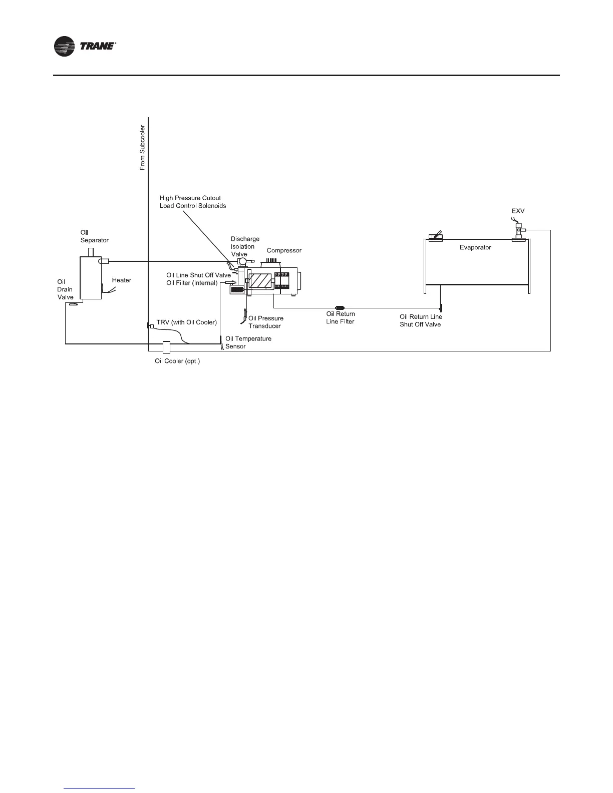
Oil system consists of the following components:
• Compressor
• Oil separator
• Discharge line with service valve
• Oil line from separator to compressor
• Oil line drain (lowest point in system)
• Oil cooler - optional
• Oil temperature sensor
• Oil line shut off valve with flare service connection
• Oil filter (internal to compressor) with flare fitting
service connection and schrader valve
• Oil flow control valve (internal to the compressor after
the filter)
• Oil return line from evaporator with shut off valve and
strainer
Refer to Table 1, p. 12 throughTable 10, p. 21 for the
standard oil charge for each circuit.
Note: Recommendation: check the oil level in the sump
using a sight glass or a manometer, attached to
charging hoses.
Figure 45. Oil system schematic
 Loading...


