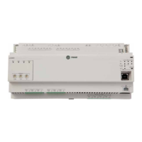
The sensor sources voltage and is powered.
Checkout Procedure Measurement Expected Value
Step 1 Measure AC voltage across the voltage input.
VAC ≈ 0.0 V
AC voltage will affect further measurement.
Step 2 Measure DC voltage across the voltage termination.
Compare the measured voltage with the
expected value based on the manufacturer’s
specification and current conditions.
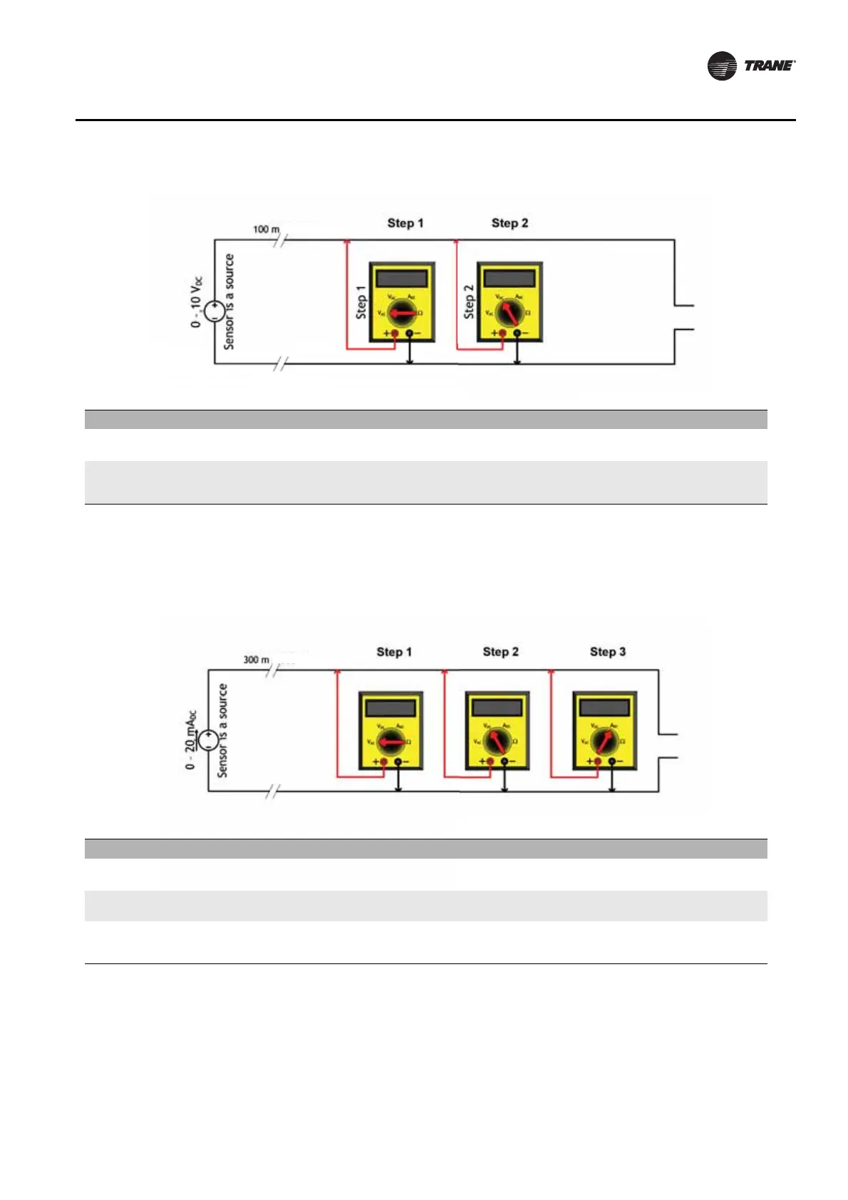
The sensor sources 4-20 mA and is powered.
Checkout Procedure Measurement Expected Value
Step 1 Measure AC voltage across the current input.
VAC ≈ 0.0 V
AC voltage will affect further measurement.
Step 2 Measure DC voltage across the current input.
VDC ≈ 0.0 V.
DC voltage will affect further measurement.
Step 3 Measure the DC current across the current input.
Compare the measured current with the
expected value based on the manufacturer’s
specification and current conditions.
 Loading...


