Measurement Procedure Expected Value
Measure DC voltage across the binary input Vdc ≤ 0.2 V (BJT = ON)
UI: Vdc ≈ 3.3 V (BJT = OFF)
AO: Vdc ≈ 22.0 V (BJT = ON)
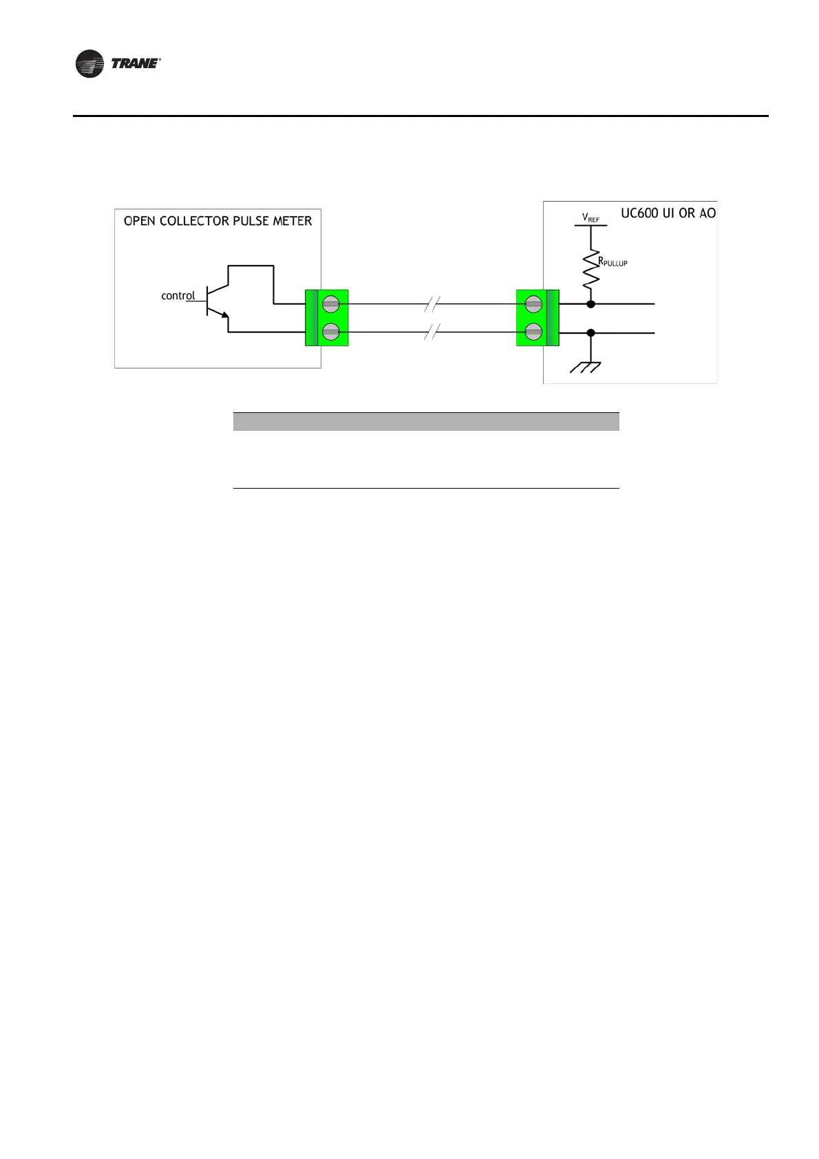
Open-collector based binary sensors use a bipolar junction transistor (BJT). This is a three-
terminal device in which emitter-to-collector current is controlled by base current as the
switching device in place of a relay. The term, open-collector, refers to the collector connection
on the transistor itself. Open-collector circuits are used for their low fatigue rate and quick
response relative to relay-based outputs.
The circuit within the pulse meter is completed when adding a pull-up resistance and reference
voltage. On the UC600, both universal input (UI) and analog output (AO) circuits add the
necessary resistance and voltage without external parts.
Note: The reference voltage must always be DC.
The voltage across the pulse meter terminals will bounce between V
sat
(saturation voltage) of
the transistor in the pulse meter and the V
ref
(reference voltage) provided by the UI or AO circuits
of the UC600. Most bipolar transistors have a V
sat
of less than 0.2 Vdc.
The DMM sampling rate may be too slow to measure pulse meter output transitions.
Note: Check the specifications of the DMM. It may be necessary to use an oscilloscope to
measure the transition voltages.