30 BAS-SVX45F-GB
Wiring Inputs and Outputs
Wiring Universal Inputs
The UC600 has a total of 14 universal input and output terminals: eight universal inputs located
on the upper tier and six universal input/output terminals on the bottom tier. Refer to Table 2, p. 9
for device connections and ranges.
Wiring Binary Inputs
Binary inputs are two-state inputs, such as fan on/off or alarm resets.
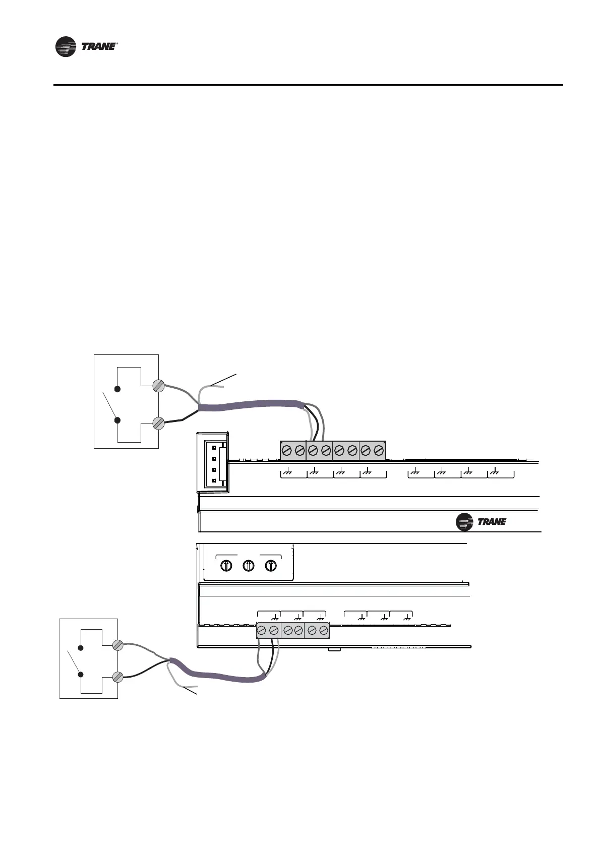
1. Connect the common wire to a common terminal as shown below.
Note: Because the common terminals are in parallel, wiring can be made to any common
terminal.
2. Connect the shield wire to a common terminal at the termination board and tape it back at the
input device.
3. Connect the signal wire to an available input terminal.
4. Use the Tracer TU service tool to configure the binary input that references the corresponding
hardware termination.
Figure 10. Wiring binary inputs
1
IM
C
UI
8
UI
7
UI
6
UI
5
UI
4
UI
3
UI
2
UI
1
U
C
600
A
O
6
UI
14
A
O
5
UI
13
A
O
4
UI
12
A
O
3
UI
11
A
O
2
UI
10
A
O
1
UI
9
ADDRESS
0
1
2
3
4
5
6
7
8
9
x1
0
1
2
3
4
5
6
7
8
9
x10
0
1
2
3
4
5
6
7
8
9
x100
Binary inputs wired to analog
outputs/ universal input
terminations
(bottom tier of the UC600).
Binary
Switch
Signal
Common
Tape back shield
Shield
Binary inputs wired to universal input
terminations (top tier of the UC600).
Binary
Switch
Common
Signal
Tape back shield
 Loading...


