BAS-SVX45F-GB 15
Installation
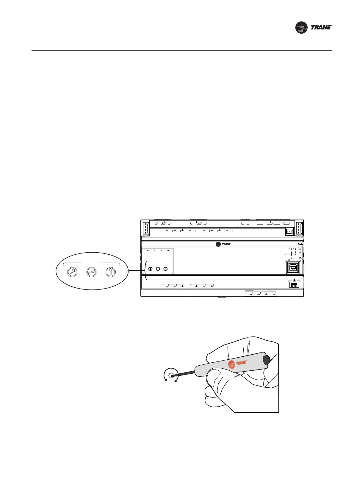
Setting Addresses using Rotary Switches
There are three rotary switches on the front of the Tracer UC600 for the purpose of defining a three-
digit address when it is installed on a BACnet communications network. The three-digit address
setting is used as both the rotary switch value and the BACnet device ID.
For Trane BACnet MS/TP systems, the rotary switch value must be between 1 and 127. Although
“0,0,0,” is a valid BACnet address, Trane reserves this address for the Tracer SC controller. For non-
Trane systems, see “Rotary Dial Address Settings for Non-Trane Systems,” p. 17. All device
addresses on the BACnet MS/TP link must be unique.
• Before powering up Tracer UC600, set the rotary switch value as shown in Figure 6.
• If the Tracer UC600 was previously powered up, do the following if you wish to make changes:
– Make the preferred changes to the rotary switch value as illustrated in Figure 6.
– Power down the Tracer UC600; when re-powered the new rotary switch value should be
active.
• For controllers that are connected through BACnet/IP, or wireless via ZigBee™, valid unit
controller rotary switch values can range from 001 to 999.
Note: Valid rotary switch values used with the Tracer UC600 are 001 to 120 for BACnet MS/TP.
Figure 6. Setting rotary switch values
0
5
1
3
6
2
9
4
8
7
A
O
6
UI
14
A
O
5
UI
13
A
O
4
UI
12
A
O
3
UI
11
A
O
2
UI
10
A
O
1
UI
9
B
O
4
B
O
3
B
O
2
B
O
1
RELAYS
0
.
5
A MAX
IM
C
1
IM
C
P
1
UI
8
UI
7
UI
6
UI
5
UI
4
UI
3
UI
2
UI
1
IMC
+
24
VDC
LINKOUT
+
24
VDC
+
24
VDC
OUT
24
VAC
MBUS
OUT
24
VAC
XFMR
24
VAC
SERVICE TOOL
SERVI
C
E
LINK
ACT
IM
C
MBUSLINK
RX
TX
U
C
600
ADDRESS
0
1
2
3
4
5
6
7
8
9
x1
0
1
2
3
4
5
6
7
8
9
x10
0
1
2
3
4
5
6
7
8
9
x100
B
O
4
B
O
3
B
O
2
B
O
1
ADDRESS
0
1
2
3
4
5
6
7
8
9
x1
0
1
2
3
4
5
6
7
8
9
x10
0
1
2
3
4
5
6
7
8
9
x100
This example illustrates the
rotary switches after addresses
have been set.
Use a 3 mm flathead
screwdriver to set rotary
switches. Dial rotates either
direction.
Important: Each Tracer UC600 device on the BACnet link must have a unique rotary switch value, otherwise,
communication problems will occur.
 Loading...


