34 BAS-SVX45F-GB
Wiring Inputs and Outputs
Wiring Trane Zone Sensors
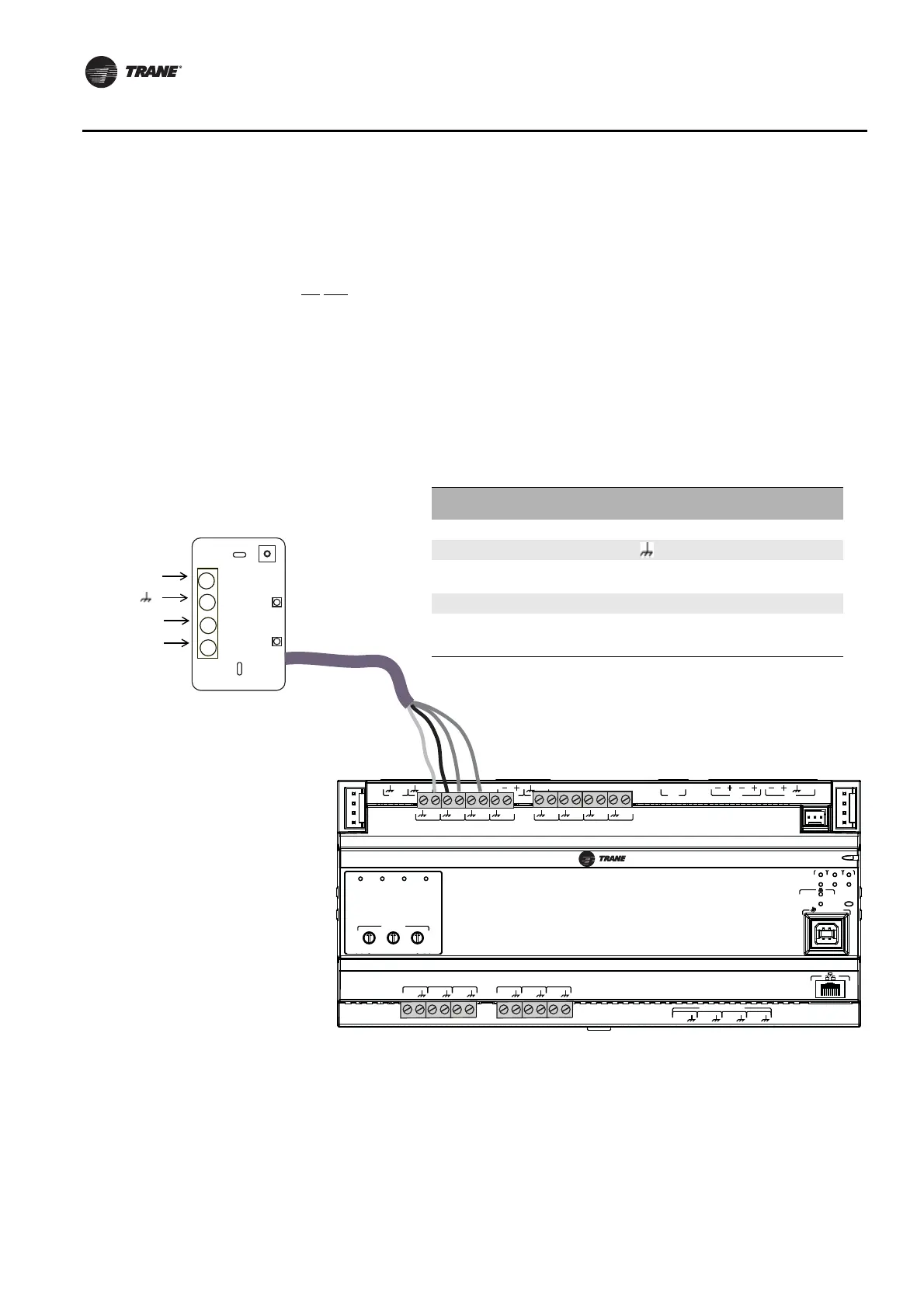
The table in Figure 14 shows the terminations on a Trane zone sensor and a typical UC600
application.
1. Connect the shield to a common terminal at the terminal board device.
Note: Do Not use the shield as the common connection. For 3-wire applications, use a
3-conductor cable with shield and for 2-wire applications, use a 2-conductor cable with
separate shield.
2. Connect the zone sensor wires to any available input (UI, UIO) terminals; refer to table 7 as an
example.
3. Use the Tracer TU service tool to configure the analog input that references the corresponding
hardware termination.
Figure 14. Typical wiring, Trane zone sensors
A
O
6
UI
14
A
O
5
UI
13
A
O
4
UI
12
A
O
3
UI
11
A
O
2
UI
10
A
O
1
UI
9
B
O
4
B
O
3
B
O
2
B
O
1
RELAYS
0
.
5
A MAX
IM
C
1
IM
C
P
1
UI
8
UI
7
UI
6
UI
5
UI
4
UI
3
UI
2
UI
1
IMC
+
24
VDC
LINK
OUT
+
24
VDC
+
24
VDC
OUT
24
VAC
MBUS
OUT
24
VAC
XFMR
24
VAC
SERVICE TOOL
SERVI
C
E
LINK
ACT
IM
C
MBUSLINK
RX
TX
U
C
600
ADDRESS
0
1
2
3
4
5
6
7
8
9
x1
0
1
2
3
4
5
6
7
8
9
x10
0
1
2
3
4
5
6
7
8
9
x100
B
O
4
B
O
3
B
O
2
B
O
1
4
3
2
1
Table 10. Example zone sensor terminations
Zone Sensor
Termination
Zone Sensor
Output
UC600
Termination
Type Range
1 Zone Temp UI1 Thermistor 10kΩ
2 Ground n/a n/a
3
Zone Temp
Setpoint
UI2 Resistive 200Ω−20kΩ
4 Fan Mode UI3 Resistive 200Ω−20kΩ
Note: Example hardware terminations. Any universal input or universal
input/analog output may be used for terminating zone temp, zone temp
setpoint, or fan mode.
Fan mode
Setpoint
Space
 Loading...


