8 BAS-SVX45F-GB
Overview
Specifications
Tracer UC600 conforms to the specifications shown in Table 1.
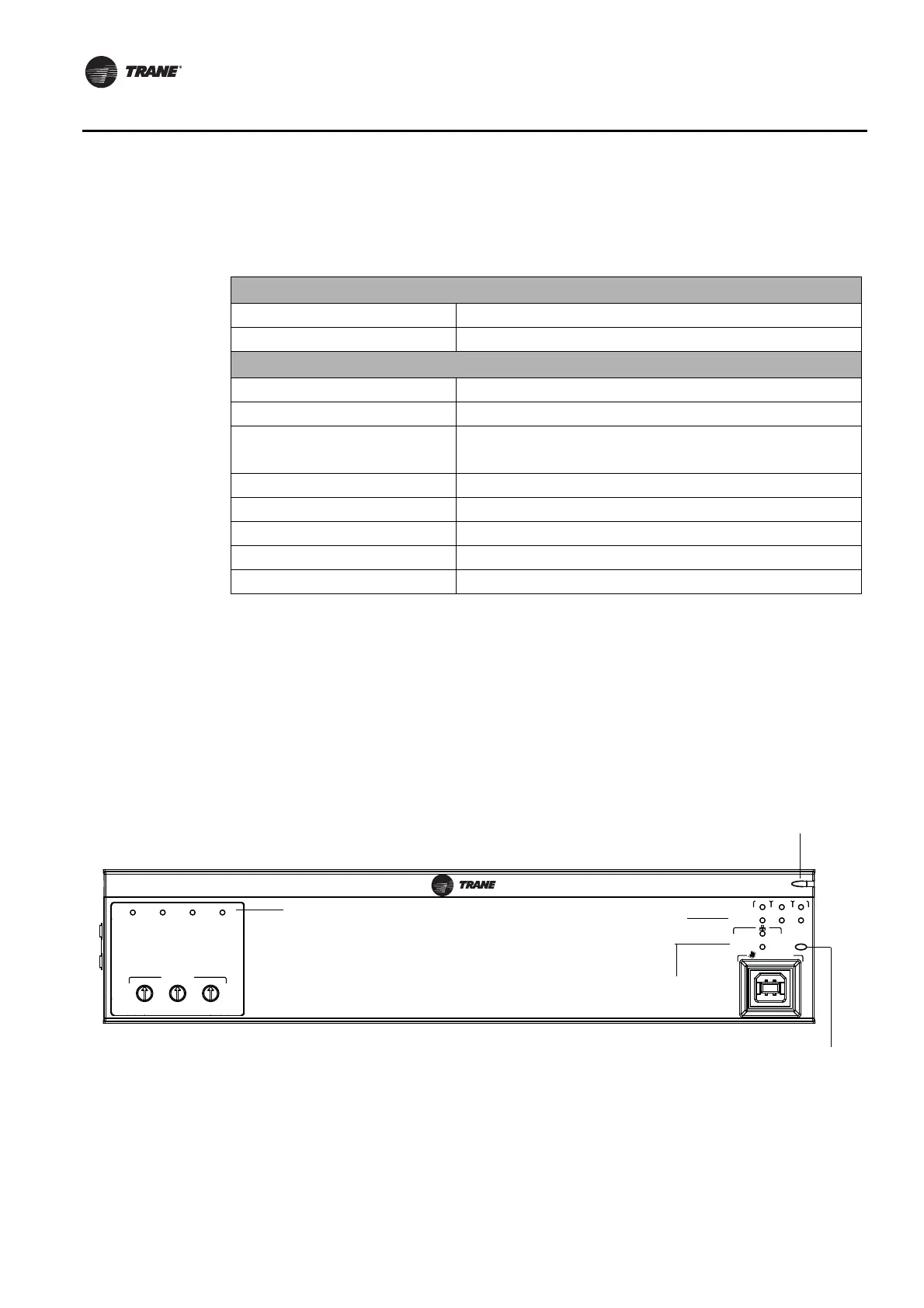
Location of LEDs
Light emitting diodes (LEDs) indicate the operation and communication status of the controller.
To interpret the Tracer UC600 LEDs and safely operate the Tracer UC600, see “LED Descriptions and
Activities,” p. 38.
For detailed information about wiring communication links, refer to Tracer SC Unit Controller
Wiring Guide (BAS-SVN03) listed in the section, “Other Resources,” p. 75.
.
Table 1. Specifications
Storage
Temperature: -55°C to 95°C
Relative humidity: Between 5% to 95% (non-condensing)
Operating
Temperature: -40°C to 70°C
Humidity: Between 5% to 95% (non-condensing)
Power:
Input: 20.4–27.6 VAC (24 VAC, ±15% nominal) 50 or 60 Hz, 26 VA
(26 VA plus a maximum of 12 VA for each binary output)
Output: 24 VDC, ±10%, device max load 600 mA
Time Clock: On-board real time clock with 7 day backup
Mounting weight of controller: Mounting surface must support 0.6 kg
Environmental rating (enclosure): IP20
Installation: UL 840: Category 3
Pollution: UL 840: Degree 2
Figure 1. UC600 LEDs
SERVICE TOOL
SERVI
C
E
LINK
ACT
IM
C
MBUSLINK
RX
TX
U
C
600
ADDRESS
0
1
2
3
4
5
6
7
8
9
x1
0
1
2
3
4
5
6
7
8
9
x10
0
1
2
3
4
5
6
7
8
9
x100
B
O
4
B
O
3
B
O
2
B
O
1
Binary output status
LEDs
Power LED
Ethernet LEDs
Communication status
(Link, MBUS, IMC)
Service button and LED
 Loading...


