30
Preparing the 12 V DC electrical
connection
All electrical connections must be made in
compliance with all national, regional or lo-
cal electrical codes.
Risk of a short circuit and hazardous situ-
ations due to improper installation of the
electrical connection!
• Use only insulated terminals for all electri-
cal connections.
• The positive line must be protected with
a 7.5A fuse (exclusively dedicated to
the appliance) near the battery’s positive
terminal.
• The power supply cable must have a diam-
eter of at least:
– 16 AWG (1.5 mm² MWG) for up to
40 ft (12 m) length (bidirectional)
– 14 AWG (2.0 mm² MWG) for up to
66 ft (20 m) length (bidirectional)
• Establish the 12 V DC electrical connections
according to the connection diagram, see
“Electrical connection for all models” on
page31.
• To ensure reliable operation:
– Provide a constant voltage supply.
– Filter any AC spikes or voltage surges.
– The AC voltage ripple must not exceed
1 Vpp.
• Make sure that the electrical connections
from the vehicle are in place before installing
the appliance.
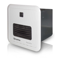
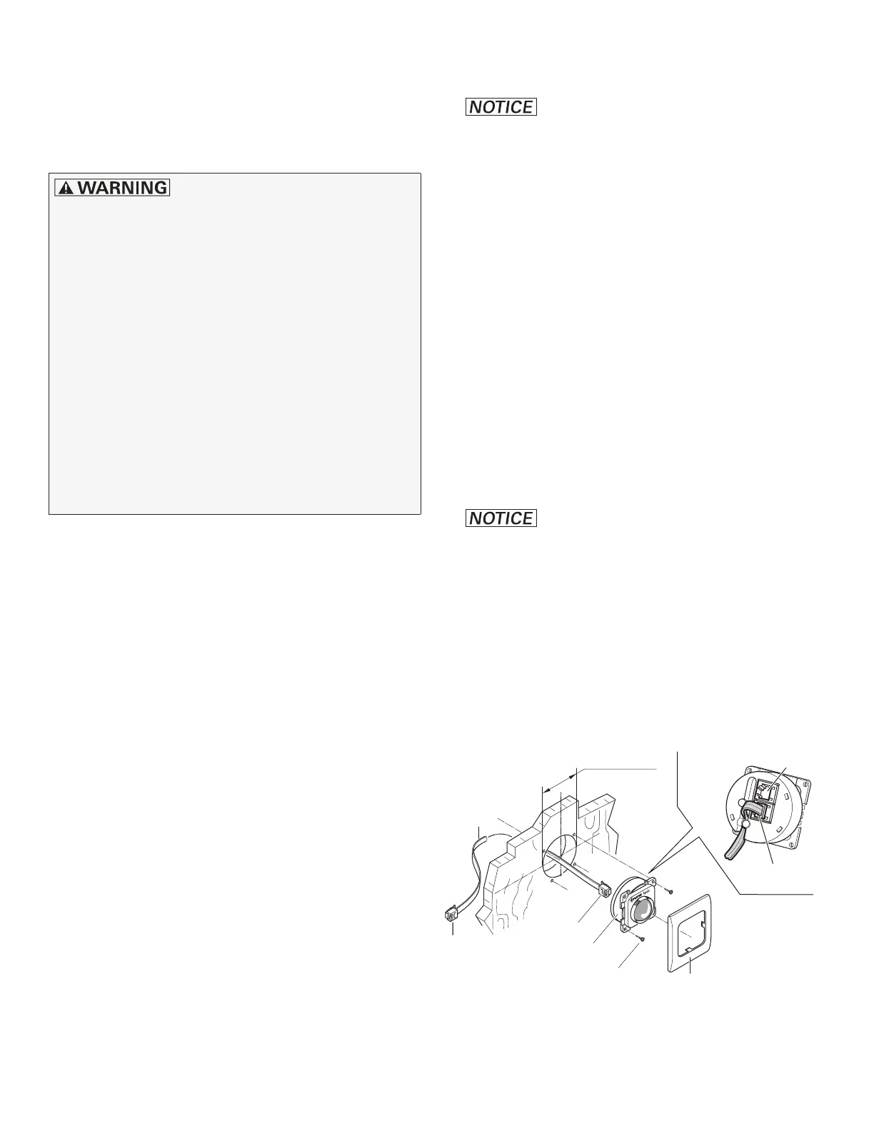
Mounting the control panel
Only AquaGo comfort / AquaGo comfort plus
• Damage to the control panel
from wetness and moisture. You must
install the control panel at a place inside the
RV that is protected against moisture and
wetness.
• Install the control panel (Fig. 17- 27) where it
can be seen easily.
– A 9 m control panel cable (27a) is includ-
ed with the delivery.
• Drill a 2 1/8 in. (54 mm) diameter hole.
• Insert the plug (27b) on the control panel (27)
until it clicks into place.
• Clamp the control panel cable (27a) in the
cable duct of the control panel.
• Damage to the control panel
cable at temperatures above +60 °C. Do
not install the control panel cable on or fix it
to hot components.
• Slide the control panel cable to the back and
lay it to the appliance.
• Fix the control panel with 4 screws (27d).
• Install the cover frame (27e).
27e
27c
Ø 2 1/8 in.
(54 mm)
27
27a
27b
27d
27b
27
Fig. 17
 Loading...