SARA-R5 series - System integration manual
UBX-19041356 - R04 System description Page 24 of 118
C1-Public
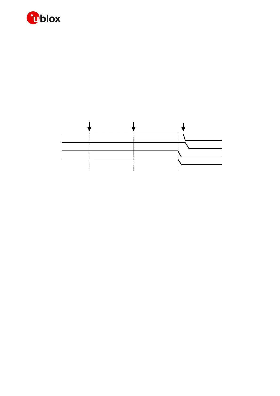
1.6.2.2 Switch-off sequence by +CPWROFF AT command
Figure 15 describes the switch-off sequence of the modules started by the +CPWROFF AT command,
allowing storage of parameter settings in the non-volatile memory and a clean network detach:
• When the +CPWROFF AT command is sent the module starts the switch-off routine.
• Then the module replies OK on the AT interface: the switch-off routine is in progress.
• At the end of the switch-off routine, all the digital pins are tri-stated and all the internal voltage
regulators are turned off, including the generic digital interfaces supply (V_INT).
• Then, the module remains in switch-off mode as long as a switch-on event does not occur
(e.g. applying a low level to PWR_ON), or enters not-powered mode if the VCC supply is removed.
Figure 15: SARA-R5 series modules switch-off sequence by means of +CPWROFF AT command
☞ It is highly recommended to monitor the V_INT pin to sense the end of the switch-off sequence.
☞ The duration of each phase in the SARA-R5 series modules’ switch-off routines can largely vary,
depending on the application / network settings and the concurrent module activities.
☞ It is highly recommended to avoid an abrupt removal of the VCC supply before that the V_INT
output of the modules goes low: VCC supply can be removed only after V_INT goes low.
☞ In case of applications where an abrupt power removal cannot be avoided, it is recommended to
set the RESET_N input line at the low logic level as soon as the power failure in the supply source
is detected, so that the under-voltage shutdown may be executed more safely since ~450 ms after
the falling edge at the RESET_N input line.
 Loading...


