Commissioning Sageon Micro Power Module Manual
PM990-4207-00, Rev. 6
3-9
3.6 BATTERY CONNECTIONS
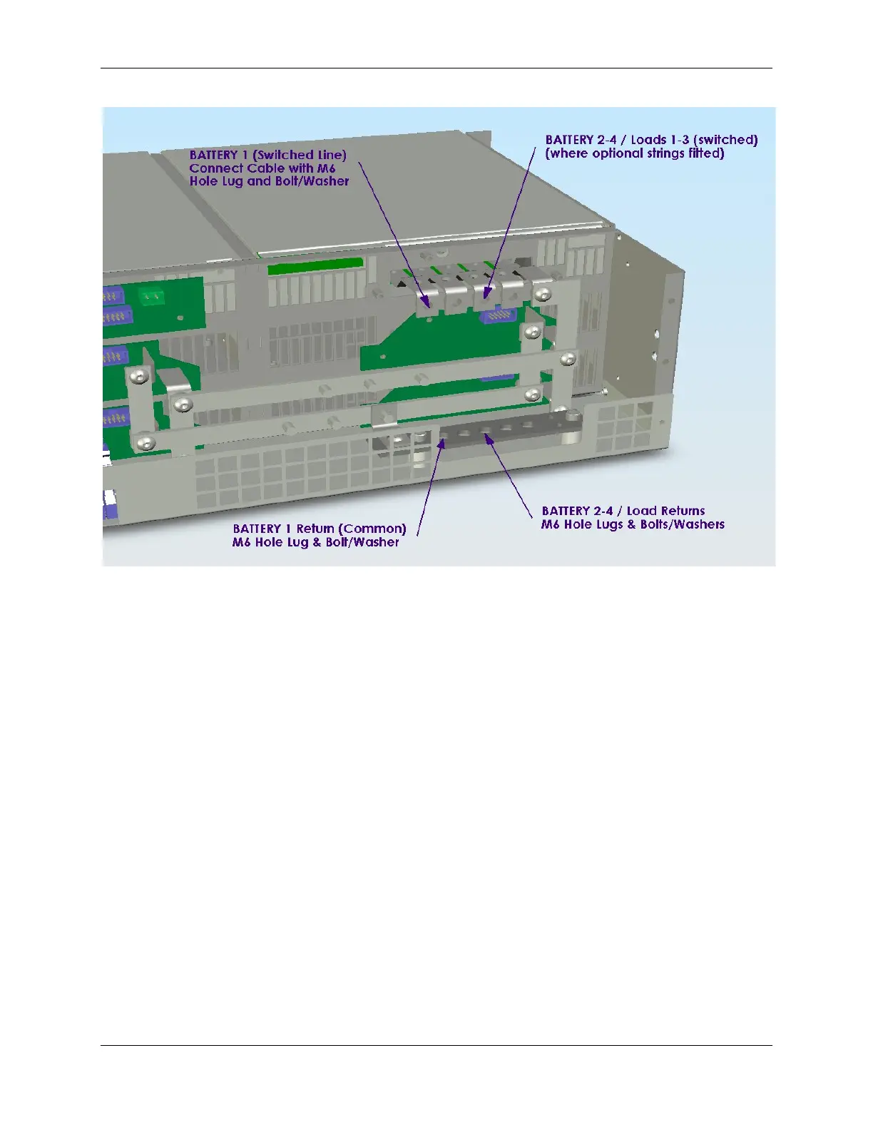
Figure 3.11 Battery Connections
For –48VDC systems, the battery negative cables are terminated on the switched line terminals of the battery
distribution module (shown above), while the battery positive cables are all tied to the common return bar. The
cables can be either brought out through the cut out adjacent to the return bar, or through the break-out slot in the top
cover.
For +24VDC systems, the battery positive cables are terminated to the battery distribution module, and the negative
cables are tied to the common return bar. The internal wiring of the +24VDC systems is different to that shown in
the figure only in the swapping of the polarity of the live and common DC lines.
In standard Power shelf systems, not all of the 4 possible battery connection strings are installed. The figure shows
a battery distribution unit fitted with all the optional battery strings possible. See BDM section below for details
about adding extra battery strings or load distribution lines to the BDM.
The M4 terminations at one end of the common return bar are available for connection of the “central office earth” –
the single point connection where the DC system is tied to the building grounding system. This cable must be sized
accordingly to carry the battery short circuit current for the time required to clear the battery protection devices.
Note: Ensure the battery circuit breakers are open before connecting the batteries. Connect the switched cable
connections first, followed by the common return cable connections.
3.7 TEMPERATURE SENSORS
The optional sensors for measuring ambient and battery temperature are the same device (Part No. 385-5941-03).
The system auto-detects if the sensor is plugged into one of the positions (4) or (5) shown in Figure 2.. If no sensor
is installed, the Controller will show “Not Available” in the menu items for the temperature measurements. Locate
the ambient sensor close to the intake air zone of the Power shelf. Locate the battery sensor on a battery block in the
middle shelf of the battery bank (likely hot zone).
 Loading...