Commissioning Sageon Micro Power Module Manual
PM990-4207-00, Rev. 6
3-14
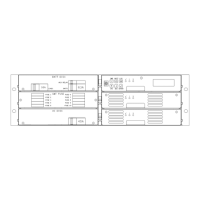
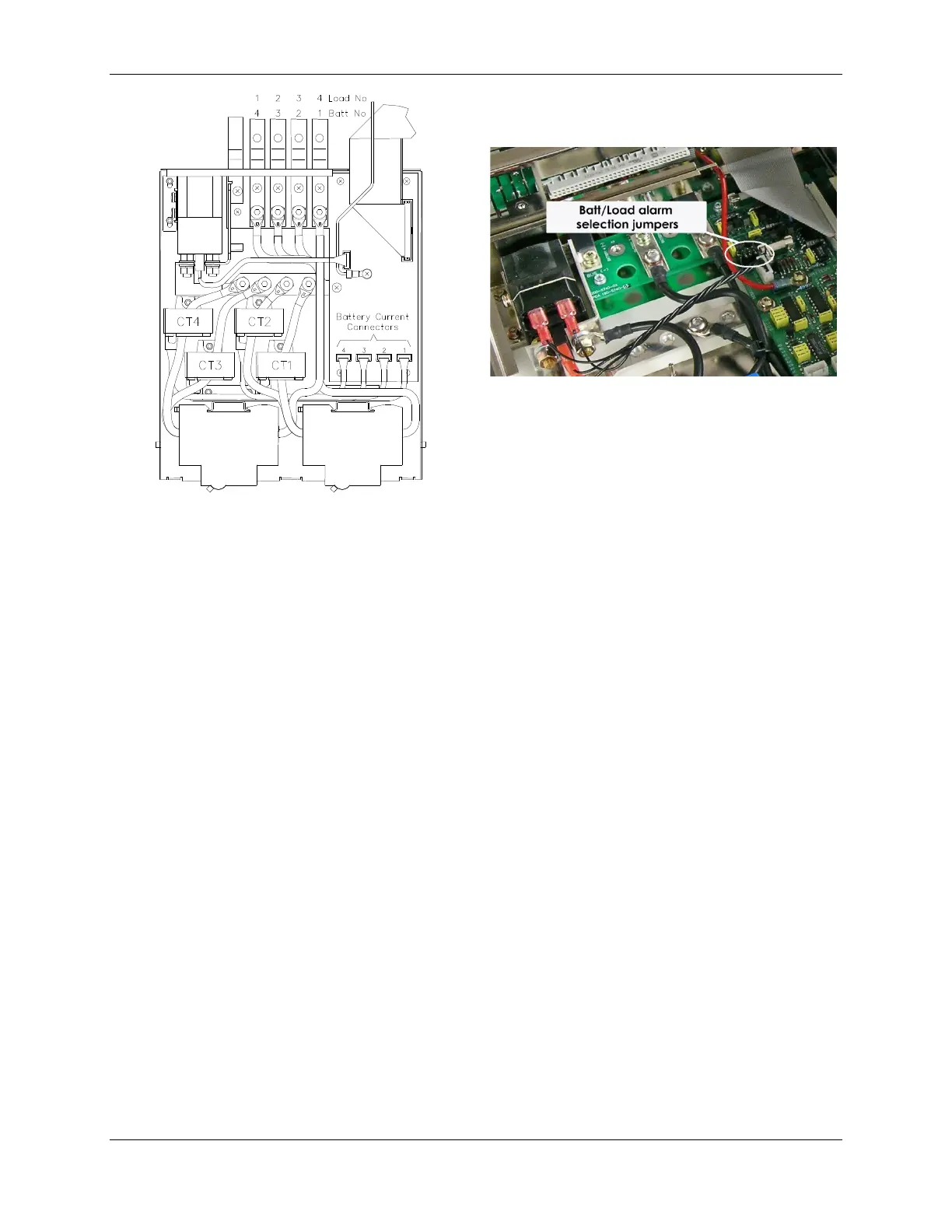
Figure 3.14 Battery String Kit Installation
Figure 3.15 Load Connection Kit Installation
To re-install the lid, slide it in on the top edge of the base until the lid mates with the rear of the BDM base. Secure
the front of the lid to the base with 2 x M3 screws.
3.13 ADDING AUXILIARY EXPANSION MODULES
Modules such as the Sageon Battery Monitor, AC monitor, and site monitor are daisy chained from the unused
ribbon cable connection provided on the Auxiliary programmable relay board. All of these expansion modules are
required to be mounted external to the Power shelf, and a single 16-way ribbon cable connected to the available box-
header.
For more detailed installation information for each of these modules, refer to the Sageon Battery Monitor Operation
Manual (PM990-4209-00) and the Sageon Site Monitor Application Note (AN103-4012-00).
 Loading...