Operation Sageon Micro Power Module Manual
PM990-4207-00, Rev 6
5-4
CSU can not reach desired system voltage. This can be due to possible
excessive voltage drop along bus bars or “System V Drop” parameter has value
One or more cells being monitored by BCM is too high in voltage
One or more cells being monitored by BCM is too low in voltage
One or more cells being monitored by BCM is too high % deviation from the
mean battery cell voltage
One or more cells being monitored by BCM is too low % deviation from the
mean battery cell voltage
RECTIFIER parameter range error. Controller could not overwrite values
Alarm present from the site monitor module. See site monitor menu for details
of alarm channel.
Batteries are discharging
Battery discharge test failed to reach a programmed end point
Alarm flags only if the system voltage falls below Discharge Alarm level while
the battery is discharging
Alarm generated for NiCad batteries using special sensor and software
One or more of RECTIFIERs are not responding
Ambient temperature higher than preset limit
Battery temperature higher than preset limit
Battery temperature sensor not connected or failure
Battery charging current is being limited to preset value
Battery discharge currents from battery strings not sharing load equally
Earth leakage current greater than the limit set
System is in equalize mode
R = red LED on A = amber LED flashing * not flashing
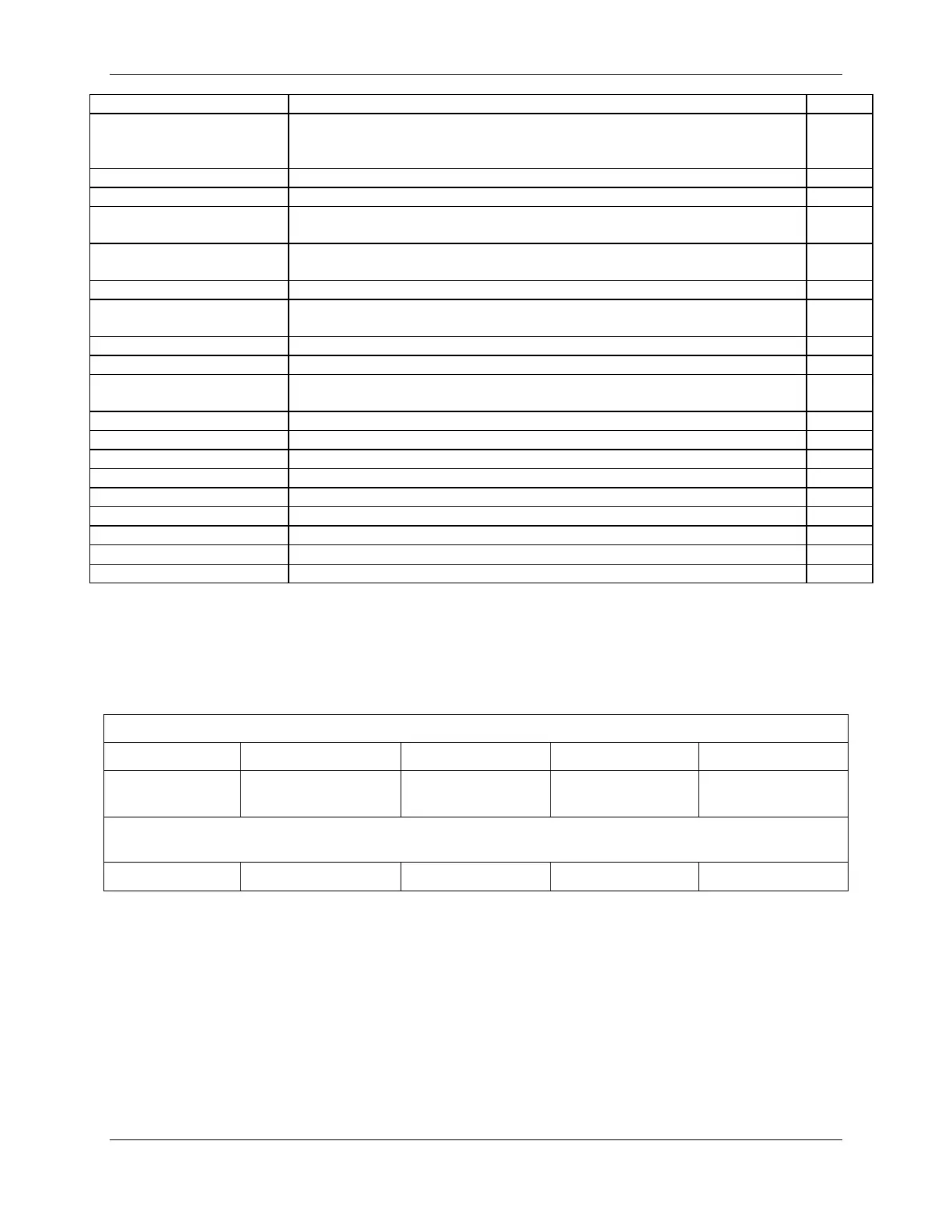
5.2.4 User programmable relay functions
Units are shipped with factory default relay assignments (see below). The relay logic of the default settings is
contact closure on an active alarm. Relay functions can be re-assigned only from a PC running monitoring program
Sageview (either through the front panel USB or remote communications port). Refer to Sageview Help for
instructions.
Relay Default Assignments
Not Assigned Not Assigned HV Shutdown General Alarm RECTIFIER
Customer Relay Assignments
 Loading...