Commissioning Sageon Micro Power Module Manual
PM990-4207-00, Rev. 6
3-10
3.8 AUXILIARY RELAY CONNECTIONS
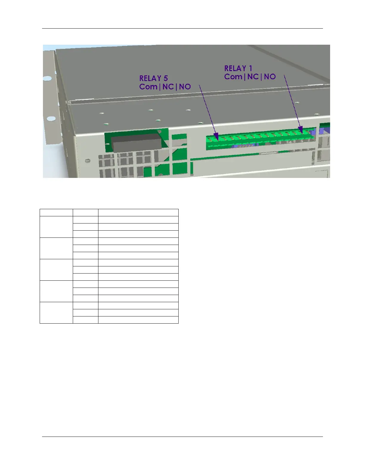
Figure 3.12 Alarm relay connections (right) and remote communications module location (left)
The user configurable auxiliary relays contacts are shown above. The contacts are rated for 1A 250VAC or 1A
32VDC and have >1kV isolation to the coils. The pin configuration is: (Pin 1 at the right in Figure 3.12)
The relays, being user configurable, can be arranged to
activate for multiple alarm conditions or a single alarm only.
The logic can be inverted for individual relays so that one
becomes a controller failure indicator (use the normally
closed contact as this will also indicate if the relay power
has failed).
3.9 CONTROLLER POWER CONNECTIONS
Power for the Controller and its peripherals is derived from the DC bus or the highest charged battery. The Battery
distribution module has reverse polarity protection circuit that also serves to provide an
“or-ing” of the highest supply voltage for the Controller. There is one common connection to the (+) bus (in the
case of a –48V system) and one connection each to the battery (-) bar on the LVDS and the (-) DC bus connection.
The system voltage is sensed and controlled solely on the connections to the DC bus (-) is sensed where it connects
to the LVDS and the (+) is sensed on the common return bar). This is considered close enough to the batteries to
enable accurate temperature compensated charging and long battery life. No additional user connections are
required to power the Controller or provide system voltage regulation, if the battery distribution module is used.
If the battery distribution module is not used, then the power for the Controller and the system voltage sensing must
be provided through the specially reserved connector on the Controller backplane, indicated as connection (7) in
Figure 2.. DO NOT use this connection if the battery distribution module is used, as it will cause a voltage sensing
conflict.
 Loading...