Commissioning Sageon Micro Power Module Manual
PM990-4207-00, Rev. 6
3-11
3.10 FRONT PANEL USB COMMUNICATIONS CONNECTION
The front USB port on the Controller is configured as USB-slave and has a B-type connector. A standard USB A-
to-B cable is required. The Controller can only communicate via the USB port to a PC running the Sageview
software.
The USB connection requires that a USB driver be installed on the PC. The first time the Controller is plugged into
the PC via the USB port, a Microsoft® Windows dialogue box will appear asking the user to install the Controller
USB Interface drivers. The Microsoft® Windows operating system should be able to find the drivers automatically
on the Sageview CD-ROM, assuming it is in the CD-ROM drive of the PC.
If Sageview is running when the unit is plugged in, a Windows dialogue box will appear asking the user if they wish
to connect to the unit immediately. Otherwise the user will need to select the Controller from the available controller
USB devices in USB section in the Connection Setup.
3.11 REMOTE COMMUNICATION CONNECTION
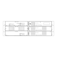
The optional remote communications modules, seen to the left of the alarm relay connectors in Figure 3.12, can be
one of the following:
P/N Description
103.4030.00 TCP/IP Interface Card
103.4031.00 Ethernet TCP/IP Interface Card w/SNMP
103.4032.00 Smart Modem
103.4033.00 RS-232 Interface
103.4034.00 RS-485 (4 wire) Interface
103.4035.00 Embedded Modem (POTS)
Embedded modems, either a standard modem or a point-to-point protocol (PPP) modem can be installed in the spare
holes with a similar mounting pattern to the alarm relay board.
The following sections describe the interfaces in more detail and cover some of the set up requirements for the more
advanced interfaces.
3.11.1 RS232 Interface
This interface should be used if the distance between the Power shelf and a monitoring PC is not greater than 50
feet. The module has standard 9-pin D-type connector. For connection to a PC a “null modem” (or “cross-over”)
cable should be used. Refer to the Operation section of this manual.
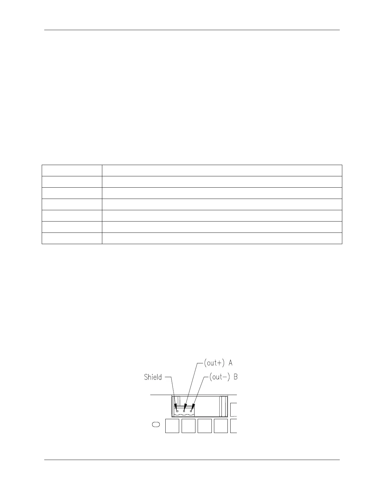
3.11.2 RS485 Interface
This type of port allows connection though a distance up to 1200 meters. Up to 32 standard devices can be linked
using twisted pair of wires. In high electrical noise environment a shielded twisted pair is recommended. The figure
below shows the pin assignment of the port.
Figure 3.13 RS485 pin assignments
 Loading...