All rights reserved 19 Servicemanual_UR10_en_3.1.3
Base joint – Base mounting bracket: Assemble
For details and photos please see: 3.1.4 General guidance to separate joint from counterpart
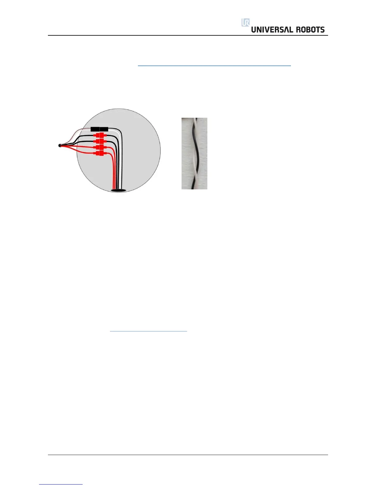
1. Replace base mounting bracket and reconnect wires according to illustration:
2. Twist the communication cable 1.5 to 2 full rounds before it is connected.
(To reduce electrical noise in the system)
3. Gently insert base mounting bracket with screws and washers into the Base joint.
4. Make sure the washers are fully inserted and flush against the head of the bolt (this is important)
before gently twisting the parts in opposite directions until a mechanical stop is met.
5. Gently tighten the 10 screws, and then tighten in cross order with 8.0Nm.
6. Slide the grey Teflon ring into place and gently put the flat ring back on top of the Teflon ring.
7. Mount the alignment screw and tighten with 0.4Nm.
8. Mount blue lid on Base joint and tighten with 0.4Nm.
9. Proceed to chapter 3.1.16 Dual Robot calibration for calibrating the robot.