UPONOR CONTROL SYSTEM WIRED - QUICK GUIDE
6
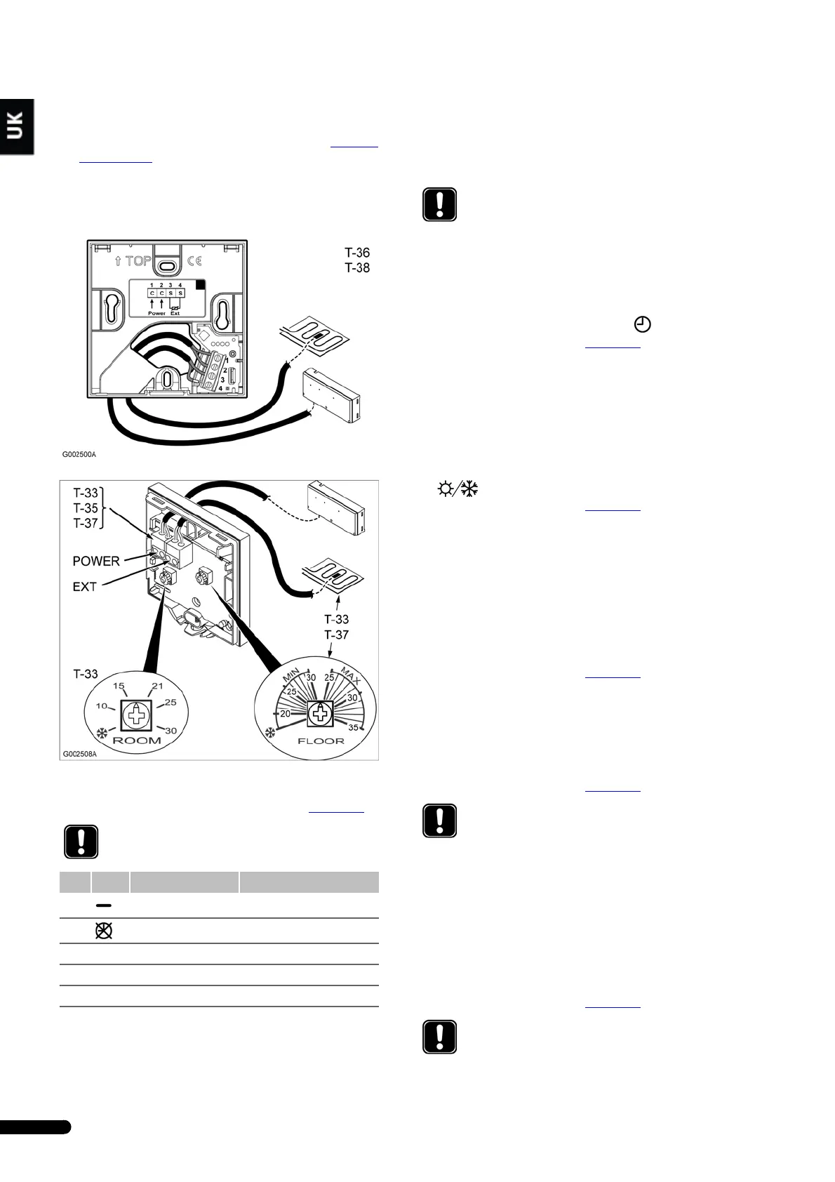
4.4 Connecting thermostats
1. Ensure that the conditions for the auto-linking function are
met when connecting the thermostats. See section 4.2
Auto-
linking, page 5.
2. In each thermostat, connect the cable to the controller to the
connector labelled Power.
In Uponor Thermostat T-34, connect to the only connector.
3. In Uponor Controller, connect one wire of the thermostat
cable to position 1 and the other wire to position 2, 3, or 4.
See table below and wiring diagram in section 4.1, page 5
.
4. If an optional floor sensor or remote sensor is used, connect
the cable to the connector labelled EXT. See illustrations
above.
5. (T-33 only) Adjust the room temperature setpoint with the
potentiometer labelled ROOM.
6. (T-33 and T-37 only) Adjust the optional floor sensor for
either a maximum temperature or a minimum temperature
with the potentiometer labelled FLOOR.
4.5 Connecting Uponor Timer I-36 (C-35
only)
To connect a timer to the controller:
1. Connect the timer to positions 1 and 2, .
See wiring diagram in section 4.1, page 5
.
4.6 Connecting a heating–cooling switch (C-
35 only)
If the installation is equipped with a cooling unit, the Uponor
Control System Wired mode can be switched with a heating–
cooling relay.
1. Connect the heating–cooling switch to positions 11 and 12,
.
See wiring diagram in section 4.1, page 5
.
4.7 Connecting a dew-point sensor (C-35
only)
If the installation is equipped with a dew-point sensor, the
Uponor Control System Wired will close the actuators for all zones
when the dew point is reach.
1. Connect the dew-point module switch to positions 4 and 5.
2. Connect the dew-point module power to positions 6 and 7.
See wiring diagram in section 4.1, page 5
.
4.8 Connecting a circulation pump
The pump output is switched on when at least one actuator is
open.
1. Connect the circulation pump to connectors labelled PUMP.
See wiring diagram in section 4.1, page 5
.
4.9 Connecting a boiler relay
In heating mode, the boiler output is switched on when at least
one actuator is open, that is a heat demand exists in at least one
zone.
1. Connect the boiler relay to connectors labelled BOILER.
See wiring diagram in section 4.1, page 5
.
NOTE!
The two wires from the thermostat are non-polarized.
Pos. Label Heating Cooling*
1 Common terminal Common terminal
2 No timer control No timer control
3* Z1 Timer control zone 1 Timer control
4* Z2 Timer control zone 2 No cooling for this room
* = C-35 only
NOTE!
All Uponor thermostats are frost protected with
minimum temperature +5 degrees.
NOTE!
There is no power in the controller to supply the
pump. The pump connector in the controller provides
only a dry contact to switch off and on the power
connection to the pump.
NOTE!
Check the boiler manufacturer's instructions before
connecting the boiler relay.
 Loading...