22 Air/flue pipe installation manual 0020308120_02
– Diameter: 125 mm
Note
If the wall duct can be accessed from the
exterior of the building, you can drill the hole
with a diameter of 110 mm and install the
wall collar from outside.
2. Slide the air/flue pipe (1) with the flexible external collar
through the wall.
3. Pull the air/flue pipe back until the external collar forms
a tight seal on the external wall.
4. Secure the air/flue pipe with mortar and leave the mor-
tar to harden.
5. Install the wall collar on the inside of the wall.
6. Connect the wall/roof duct to the product using exten-
sions, elbows and, if required, a sliding sleeve, see
"Connecting the product".
5.7.4 Installing the roof duct
▶ Insert the air/flue pipe (1) without the external collar into
the dormer.
5.7.5 Connecting the product
1. Install the product (7) – see the installation instructions
for the product.
2. Connect the 87° elbow (1) to the connector for the
air/flue pipe (6).
3. Fit the sliding sleeve (3) with the sleeve as far as it will
go onto the wall/roof duct (4) or the extension (5).
4. If required, install the extensions .
5. Connect the sliding sleeve to the 87° elbow.
6. Install the air pipe clamp (2) for the sliding sleeve.
7.
Alternatives 1:
Condition: Wall/roof duct without extension
▶ Install the sliding sleeve. (→ Page 46)
7.
Alternatives 2:
Condition: Wall/roof duct with extension
▶ Install the extensions. (→ Page 46)
▶ Install the elbows (→ Page 49).
▶ Install the sliding sleeve. (→ Page 46)
▶ Connect all of the pipe joints with air pipe clamps.
(→ Page 54)
5.8 Installing terminal sets for 60/100 mm
diameter air/flue systems
5.8.1 Minimum clearances for the flue gas terminal
You must comply with the minimum clearances for the flue
gas terminal that are defined in BS 5440, unless the boiler's
manufacturer has given approval to use shorter minimum
clearances that are not considered to be safety-critical.
Vaillant has reduced the minimum clearances for the flue
gas terminal and specifies this in the installation instructions
for the boiler. These are minimum clearances that are to be
used for all types of installation, except for the installation of
the variable terminal set (VTK).
If a variable terminal set is connected to horizontal flue pipe-
work, terminal clearances are reduced for the air inlet. The
terminal clearances on the "new" flue outlet at the end of
VTK remain unchanged.
On the VTK, the minimum clearances for the air inlet A, B
and C (→ Installation instructions for the boiler) to openings
(e.g. a window) are reduced to 150 mm. This means that
the terminal will be at the horizontal flue pipework when a
variable terminal set is connected to the air inlet and can
therefore be installed at a clearance of less than 300 mm
from a window opening or a ventilation tile.
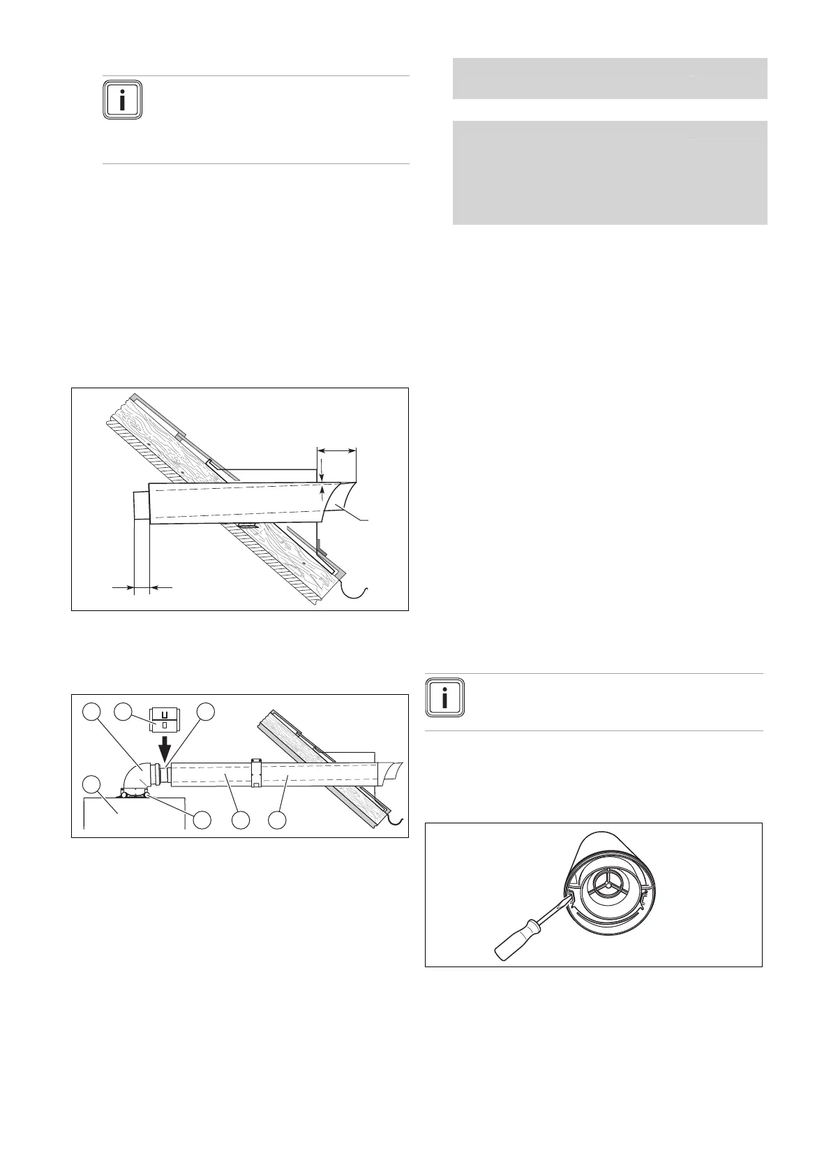
5.8.2 Removing the terminal
Note
You can install the terminal set before or after you
install the flue pipework.
1. If required, before starting the installation work, decom-
mission the boiler and secure it against being inadvert-
ently started up again.
2. If required, remove the wall duct from the terminal.
3. Use an 8 mm screwdriver to press the latching lugs
inwards.
 Loading...


