8 Air/flue pipe installation manual 0020308120_02
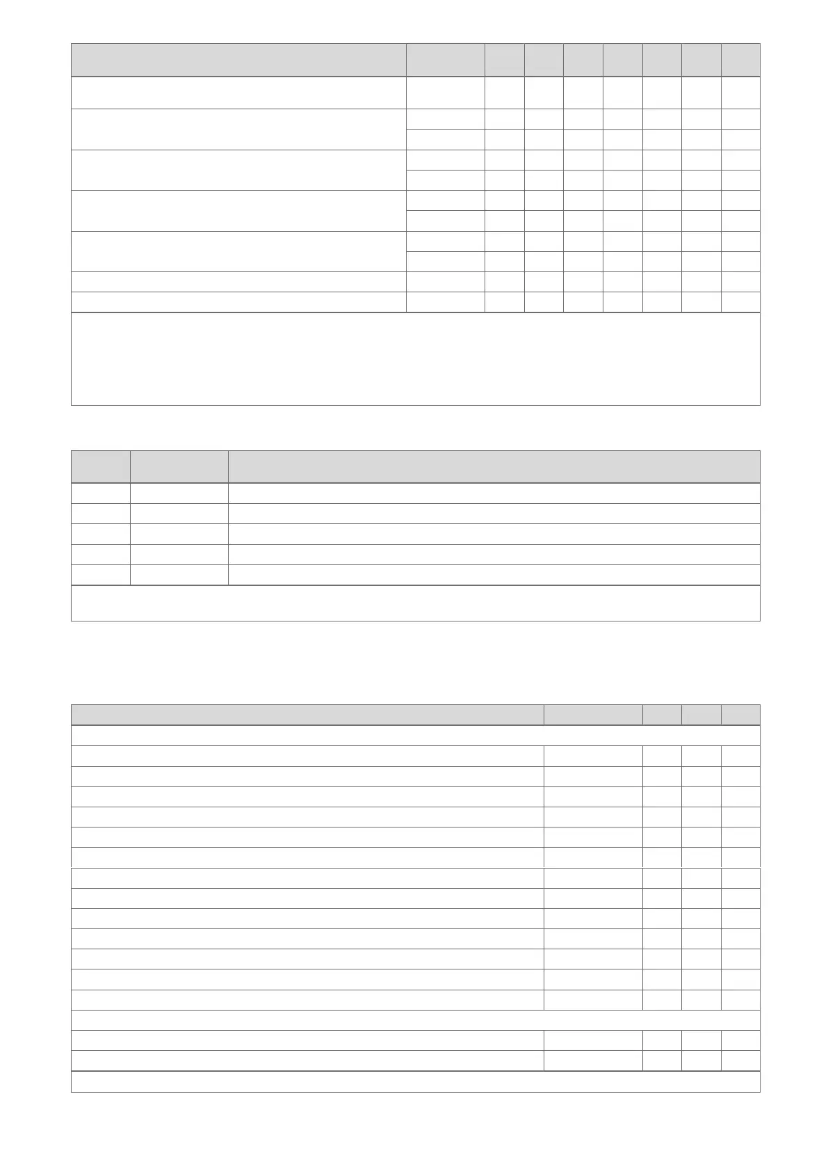
Optional connection accessories Article num-
ber
A B C, E D F G H
Extension for variable terminal set (VTK), 60 mm diameter, 1 m,
white ²
303947 X
87° elbow for variable terminal set (VTK), black ² 0020219543 X X
303944 X X
87° elbow for variable terminal set (VTK), white ² 0020219544 X
303949 X
45° elbow (2 pcs) for variable terminal set (VTK), black 0020219551 X X
303945 X X
45° elbow (2 pcs) for variable terminal set (VTK), white 0020219552 X
303948 X
Deflector set, DN 60, PP, black 0020060584 X
Deflector set, DN 60, PP, white 0020060585 X
1) To reduce the pipe connections that need to be inspected, 4 m extensions are offered on request. (Special delivery with minimum
purchasing quantity. No returns accepted.) The required downward gradient is also 3°. A height of 200 mm is therefore required for the 4
m extension. Take the height into consideration when selecting the installation site.
2) Delivery with pipe clamps
3 In accordance with the construction regulation, installation on the external wall in buildings higher than 18 m (11 m in Scotland) is per-
mitted. The sleeve end of the extension must protrude at least 60 mm from the wall to comply with fire-protection requirements.
3.2 System overview, 80/125 mm diameter
System
group
Article number Air/flue systems, concentric
A 303200 Vertical roof duct
B 303209¹ Horizontal wall/roof duct
C 0010035777² Horizontal wall duct, stainless steel
D 0010039735² External wall connector
E 0020042748¹ External wall connector
1) In accordance with the construction regulation, installation in buildings higher than 18 m (11 m in Scotland) is not permitted.
2) In accordance with the construction regulation, installation in buildings higher than 18 m (11 m in Scotland) is permitted.
3.2.1 Components
The following table lists the air/flue systems that are permitted as part of the system certification, along with their certified
components.
Optional connection accessories Article number A B, C D, E
System, concentric, 80/125 mm diameter
Connector (screw holes, 4 x) 303926 X X X
Connector with bayonet connection 0020147469 X X X
Extension (PP), concentric, 470 mm, 80/125 mm diameter 303202 X X X
Extension (stainless steel), concentric, 960 mm, 80/125 mm diameter ¹ 0010035778 X
Extension (PP), concentric, 970 mm, 80/125 mm diameter 303203 X X X
Extension (PP), concentric, 1970 mm, 80/125 mm diameter 303205 X X X
45° elbow (x 2), concentric, 80/125 mm diameter 303211 X X X
87° elbow, concentric, 80/125 mm diameter 303210 X X X
Pipe clamp (5 pcs), 125 mm diameter 303616 X X X
Sliding sleeve, 80/125 mm diameter 303215 X X X
Pitched roof tile, black 009076 X X
Universal pitched roof tile 303980 X X
Flat roof penetration collar 009056 X X
System, concentric (stainless steel), 80/125 mm diameter
External wall console, adjustable from 50 to 300 mm, stainless steel 0020042749 X
External wall pipe bracket (stainless steel), 50–90 mm 0020042751 X
1 In accordance with the construction regulation, installation on the external wall in buildings higher than 18 m is permitted
 Loading...


