INSTALLATION Series
18/116
Edition 2018-08-20 605262EE
Controller:
4.2.3 Installation procedure
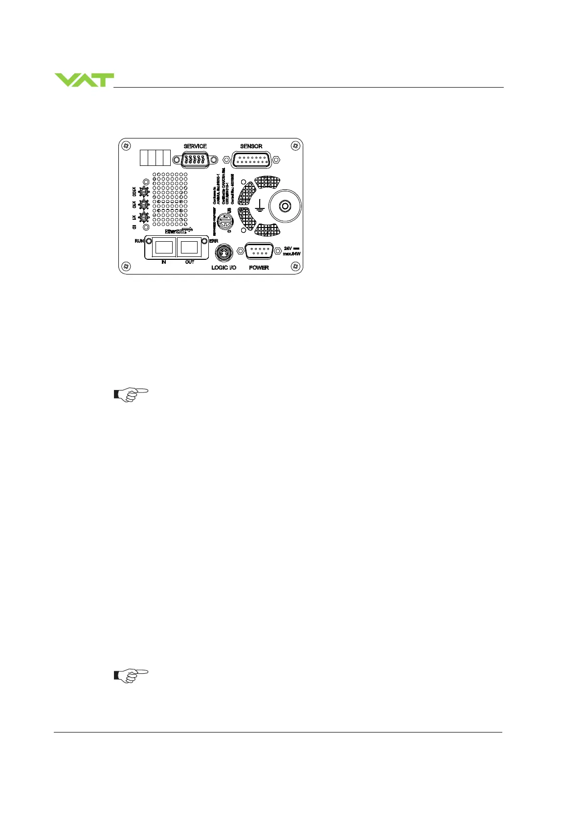
All numbers in brackets refer to chapter: «Connection overview».
1. Remove protective covers from body flanges.
2. Install [1] valve into the vacuum system.
•
Do not tighten the flange screws stronger than indicated under chapter «Tightening
torque».
•
Do not admit higher forces to the valve than indicated under chapter «Admissible
forces».
•
Make sure that enough space is kept free to do preventive maintenance work. The
required space is indicated on the dimensional drawing.
•
Control unit of valves with ISO-KF (612 . . – K . . .) needs support when mounted
on horizontal piping and control unit does not hang.
3. Install the ground connection cable at controller. Refer to chapter «Electrical connection».
4. Install sensor(s) [4] according to the recommendations of the sensor manufacturer and directives
given under chapter «Requirements to sensor connection».
5. Connect sensor cable [5] to sensor(s) and then to valve (connector: SENSOR). Refer to chapter
«Electrical connection» for correct wiring.
6. Connect valve with cable [7] to remote control unit (connector: INTERFACE). Refer to chapter
«EtherCAT connection» for correct wiring.
7. Connect power supply cable [8] to valve (connector: POWER). Refer to chapter «Electrical
connection» for correct wiring.
To provide power to the valve motor pins 4 and 8 must be bridged, otherwise motor
interlock is active and the valve enters the safety mode and is not operative. Refer
also to chapter «Safety mode».
 Loading...


