Series 642 INSTALLATION
742280ED Edition 2017-11-24 19/
Tight
en
moun
ting
screws of the flanges uniformly in crosswise order. Observe the maximum torque
levels in the following tables.
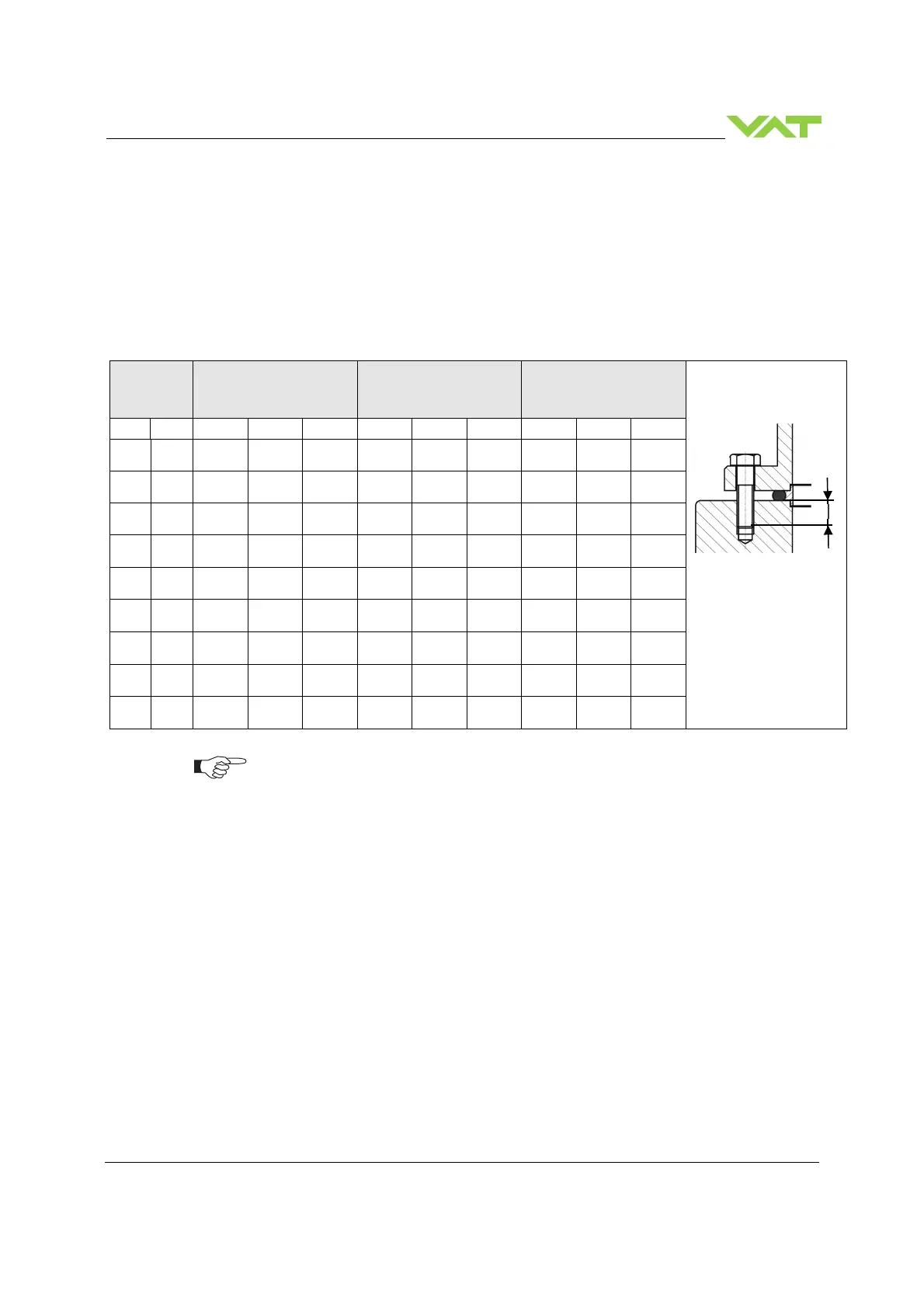
4.3.1 Mounting with centering rings
DN
max. torque
(Nm)
max. torque
(lbs . ft)
Max. hole depth [d]
(mm)
mm inch ISO-F JIS ASA-LP
ISO-F JIS ASA-LP
ISO-F JIS ASA-LP
63 2 1/2 8 – 10 8 – 10 8 – 10 6 – 8 6 – 8 6 – 8 13 13 15
80 3 8 – 10 8 – 10 8 – 10 6 – 8 6 – 8 6 – 8 13 13 15
100 4 8 – 10 8 – 10 8 – 10 6 – 8 6 – 8 6 – 8 13 13 15
160 6 13 – 15 13 – 15 20 - 30 9 - 11 9 - 11 15 – 22 14 14 15
200 8 13 – 15 13 – 15 20 - 30 9 - 11 9 - 11 15 – 22 16 16 20
250 10 17 – 20 17 – 20 40 – 60 13 – 15 13–15 30 – 44 16 16 20
320 12 17 - 20 17 – 20 40 - 60 13 – 15 13–15 30 - 44 16 16 20
350 12 17 - 20 17 – 20 40 - 60 13 – 15 13–15 30 - 44 16 16 20
400 16 17 – 20 30 – 35 55 – 80 13 – 15 22 – 26 41 – 59 25 25 NA
high. Therefore for other friction coefficients the torque needs to be adapted. Please
review design guidelines for Helicoil-Screw connections and make sure that screws in
use are capable to withstand applied torques, are appropriate for the application and
are not too long. Too long screws may damage the valve, the immersion depth should
Refer to «Spare parts / Accessories» for centering rings ordering numbers.
 Loading...


