DESCRIPTION OF PRODUCT Series
8/119
Edition 2017-11-24 742280ED
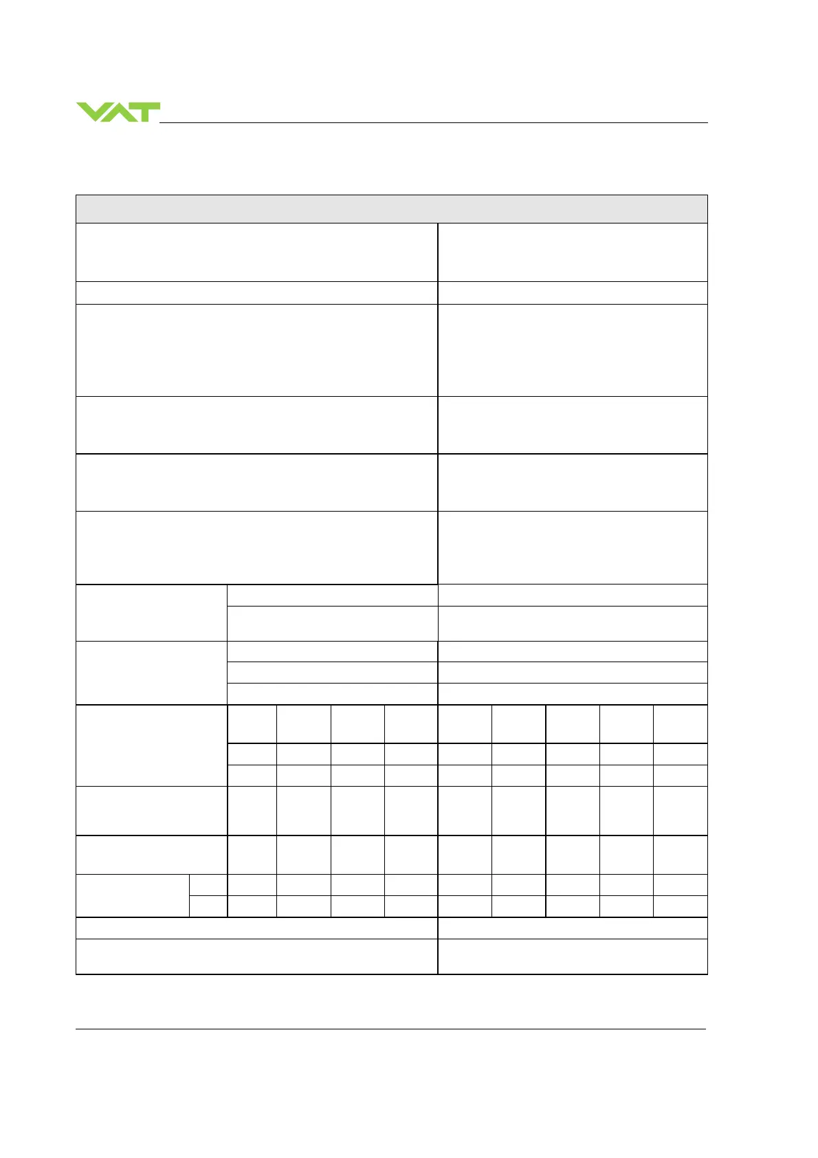
1.6.2 Valve unit
Description
Pressure range at 20°C (unheated on delivery)
• DN63…200
• DN250…400
1 × 10E-8 mbar to 2.0 bar (abs)
1 × 10E-8 mbar to 1.2 bar (abs)
Leak rate to outside / seat at 20°C (unheated on delivery)
1 × 10E-9 mbar ls
-1
Differential pressure on the gate
• Valve closed
- DN63…200
- DN250…400
• During closing / opening
≤ 2.0 bar
≤ 1.2 bar
≤ 30 mbar
Cycles until first service (unheated and under clean conditions)
• Pressure control
• Isolation cycles
1’000’000
200’000
Admissible operating temperature
• Valve body
• Ambient
≤ 150°C
≤ 150°C
Mounting position (valve seat to face chamber is recommended)
• DN63…350
• DN400
Any
Horizontal only (optional in vertical position with
extended closing time, fewer cycles)
Process side materials body / plate Stainless steel: 304 (1.4301)
other parts
Stainless steel: 301 (1.4310), 304 (1.4301),
420 (1.4034), 420D (1.4037), 430 (1.4016)
Seals plate FKM (e.g. Viton
®
)
rotary feed through FKM (e.g. Viton
®
)
bonnet FKM (e.g. Viton
®
) (DN63…200 vulcanized)
Operating time (s) for:
DN 63
2½"
DN 80
3"
DN 100
4"
DN 160
6"
DN 200
8"
DN 250
10"
DN 320
12"
DN 350
14"
DN 400
16"
Open / close 4 4 6 6 6 10 10 10 10
Pressure control
(throttling)
3 3 3 5 5 9 9 9 9
Min. controllable
conductance (ls
-1
)
[N
2
molecular flow]
0.65 0.8 1 1.6 2 2.5 3.2 3.5 4
Max. Conductance (ls
-1
)
[N
2
molecular flow]
440 800 1700 5000 12000 22000 30000 40000 50000
Weight (approx.)
kg 14 14 17 28 34 62 112 120 155
lbs 31 31 37 62 75 136 246 264 340
Valve position indication Visual (mechanical and on controller)
Dimensions
Refer to dimensional drawing of specific valve
ordering number (available on request)
 Loading...


