OPERATION
Series
88/119
Edition 2017-11-24 742280ED
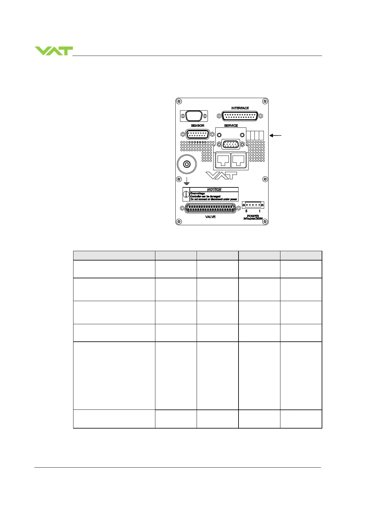
5.2 Display information
There is a 4 digit display located on
the panel. It displays configuration,
status and position information. For
details see following tables.
5.2.1 Power up
Description Digit 1 Digit 2 Digit 3 Digit 4
● Power On:
All dots are illuminated
# # # #
● 1
st
information for about 3s:
Firmware generation
[e.g. 1G..]
1 G
● 2
st
information for about 3s:
Firmware version and firmware
revision [e.g. 00 06]
0 0 0 6
● 3
nd
information for about 3s:
Valve type [e.g. 642]
6 4 2
● 4
nd
information for about 3s:
Controller configuration
In case D999 is displayed,
motor interlock is active. Refer
to «Safety mode» for details.
2
= RS232
interface
3
= RS232
interface
with analog
outputs
0
= basic
1
= with SPS
1)
2
= with PFO
2)
3
= with SPS
1)
and PFO
2)
1
= 1 sensor
version
2
= 2 sensor
version
SYNC indicates that powerup
synchronization is running.
S
Y
N C
1)
SPS = optional ±15 VDC Sensor Power Supply module,
2)
PFO = Power Failure Option
1 2 3 4
Display
 Loading...


