OPERATION
Series
82/119
Edition 2017-11-24 742280ED
5.1 Normal operation
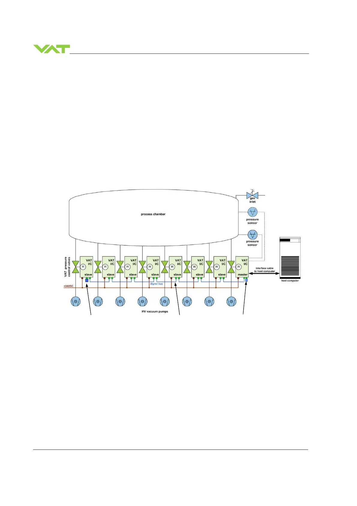
The valve cluster solution is designed to operate multiple valves (exhaust lines) installed on a single
process chamber in parallel. The system consists of one Master valve and a number of Slave valves. A
valve cluster can have up to 255 valves. Each valve in the Cluster has a unique cluster address (see
chapter «Cluster address configuration (setup step 2)» for details). A digital field bus system is used for
the inter communication between the Master and the Slave valves.
The Master valve is taking care of the pressure control, while the Slave valves are following the Master
valves plate position. It can be operated in pressure control mode or in position control mode. In both
cases local or remote operation is possible.
Therefore the host system mainly communicates with the Master valve. The Master valve then takes care
of controlling the Slave valves. All status information about the condition of each individual valve in the
Cluster can be requested from the Master valve.
For basic operation of the valve cluster the known standard command set is used. In addition there are
special commands available for getting status information of each valve connected to the Cluster. Further
it is possible to control individual Slave valves independently. For example, it is possible to close a single
valve, while the valve cluster is still operational. There is also a parameter (Position offset) for fine tuning
single exhaust lines.
120Ω terminator category 5 cables 120Ω terminator
valve cluster daisy chain
5.1.1 Individual valve control
This function is available on the Master valve only.
It is possible to individually control any valve in the valve cluster.
When commanding an individual valve to a certain position, make sure the target valve is set to ‘Freeze
mode’ previously (refer to chapter «5.1.3 Freeze mode»), so it will listen to individually addressed
commands and execute them. Once set to Freeze Mode the valve will execute any command addressed
directly to it, until it is released from Freeze Mode. Refer to chapter «Control commands» > «INDIVIDUAL
VALVE CONTROL» for details.
 Loading...


