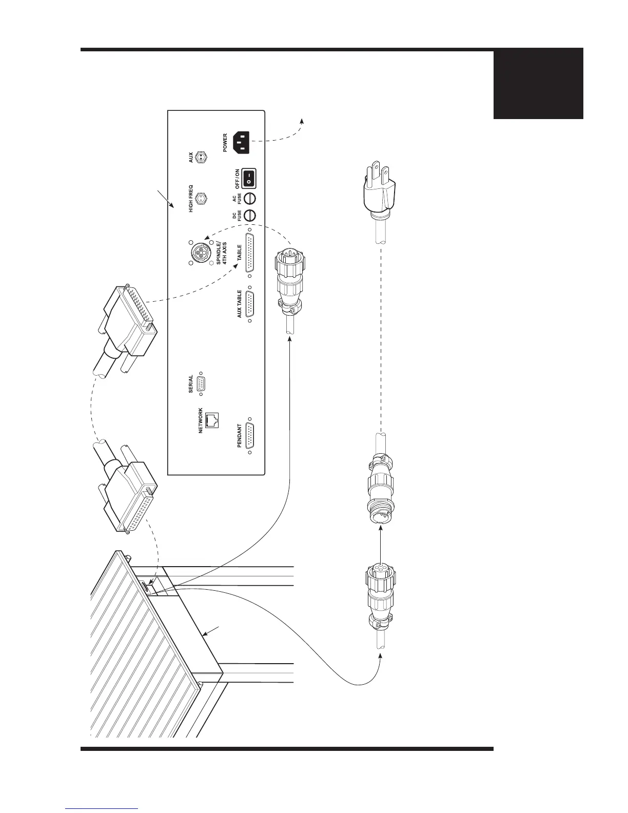
25 Pin Table Cable showing the “Female” end on the
left. This connects with the Router Table. The “Male”
end (on the right ) connects to the interface labelled
“TABLE” on the Vision 3 Serial Controller.
Spindle/4th Axis Cable showing the “Male” end. This connects
from the Router Table to the interface labelled “SPINDLE/4TH
AXIS” on the Vision 3 Serial Controller.
Spindle/4th Axis Cable showing the “Female” end. This connects
from the Router Table with the “Male” end of the Porter Cable
AC Power Cable.
This is the Plug end of the Porter Cable AC Power Cable. This is
plugged into a regular, three prong electrical outlet.
Vision 3 Serial Controller
Router Table
Schematic Diagram showing the Cable Connections for the
Porter Cable Router on the 2424/ 2448 Router Table
(Items shown are not to scale.)
To electrical
outlet
This is the “Male” end of the Porter Cable AC Power Cable.
 Loading...