Chapter 1
3. T-Slot Table. Also referred to as the work surface, this aluminum bed supported by the
linear rails allows placement of the engraving material or special clamps and xtures. The
slots in this table are shaped with an upside-down T, with the bottom of the T being a single-
line slot across the top of the table (see g 1.1b). The slots are used to hold various accessory
holders, clamps, and jigs. All t-slot accessories are avaiable on at ww.visionengravers.com
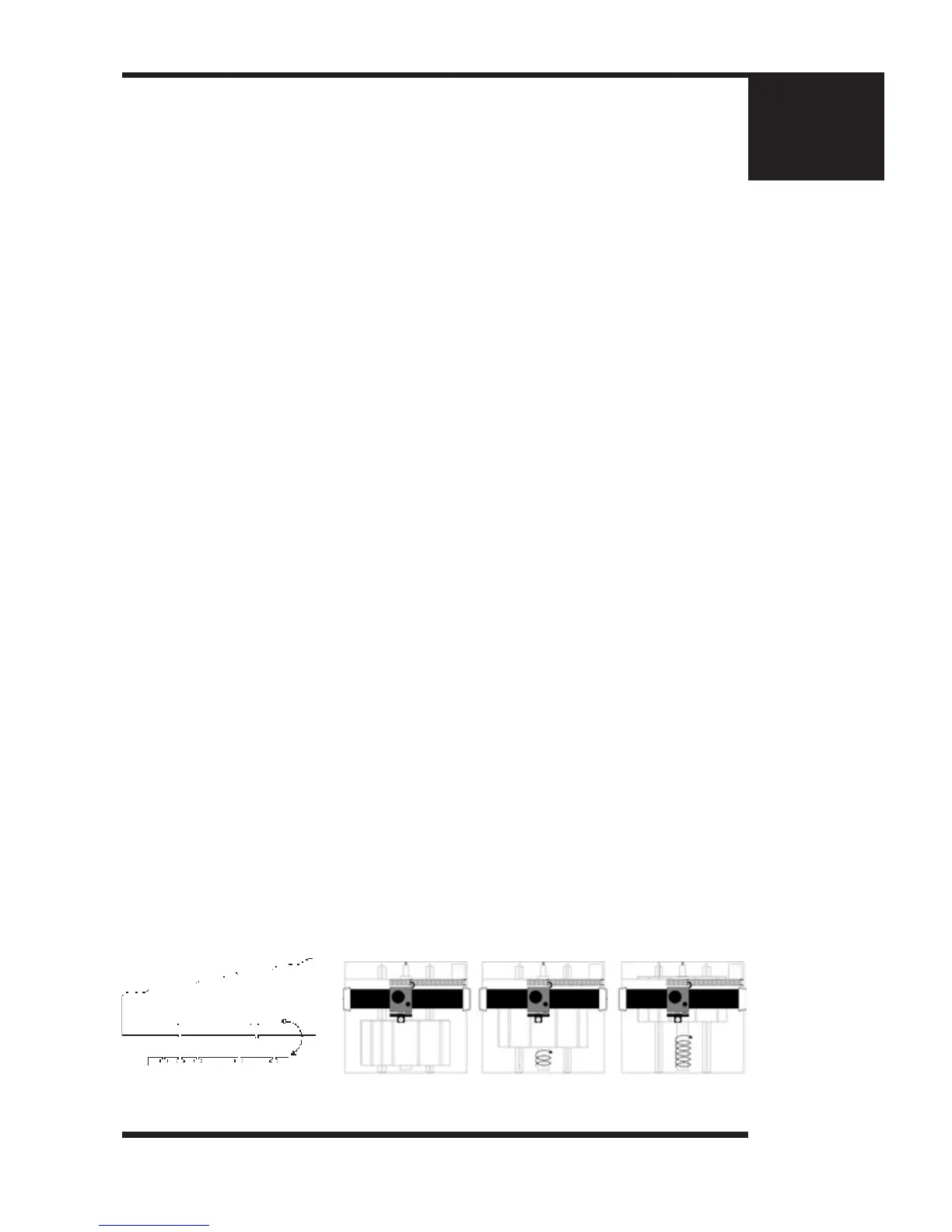
4. Y-Axis Lead Screw. This is a threaded rod located underneath the T-slot table. Combined
with the stepper motor, the lead screw is rotated and causes the T-slot table to move along
the rails in the Y-axis direction (as seen in gure 1.1c). There is also a second lead screw
called the X-axis lead screw. The X-axis lead screw is contained within the gantry, and can be
accessed by removing the black sheet metal gantry cover. The X-axis lead screw is responsible
for X-axis motion of the carriage assembly, moving it left and right across the gantry.
5. Gantry Assembly. The gantry or “bridge” is a large, rectangular bar suspended across
the width of the table in the X-axis. The carriage assembly is supported and rides on the
gantry in the X-axis.
6. Carriage Assembly. The carriage assembly houses the engraving spindle, Z-Axis
mechanism and engraving motor. The carriage moves along the gantry assembly on a set of
sealed bearing. The carriage assembly holds the engraving spindle; it raises and lowers the
spindle during the engraving process using a lead screw and stepper motor.
7. 25 Pin Breakout Box. This electrical access is used to connect the table to the system
controller. The breakout box and connector are located near the rear of the table and under
the base plate. (see page 13, g 2.1).
8. Y-Axis Stepper Motor. Drives the T-Slot table in the Y-Axis.
9. X-Axis Stepper Motor. Drives the carriage in the X-Axis. Located under the protective
sheet metal cover.
10. Material Guides. Used as a back and side stop for accurately locating material and
clamps during set-up.
11. Engraving Motor. Drives the spindle for rotary engraving.
12. Quick-Lock Vise. A “cam” type locking device that allows quick change of parts for
engraving.
(Figure 1.1c) T-slot table motion
(Figure 1.1b) T-slot close up
 Loading...