Chapter 1
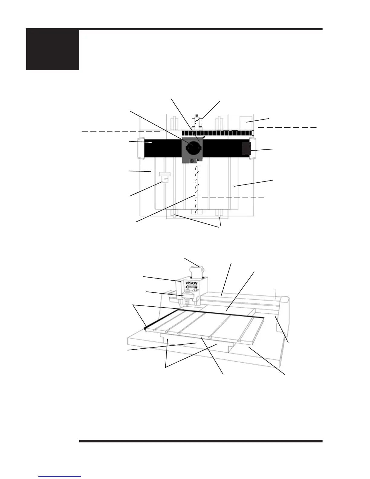
(Figure 1.1) Moveable T-slot table format.
Shown here is the top view of the Vision 1624. The Vision 1612 has a similar design.
1. Table Base Plate
2. Y-Axis Linear Rails
5. Gantry Assembly
6. Carriage Assembly
7. 25 Pin Breakout
Box (underneath)
8. Y-Axis Stepper Motor (underneath)
4. Y-Axis Lead Screw
(under metal cover)
11. Engraving Motor
3. T-Slot Table
7. 25 Pin Breakout
Box (under cover)
1. Table Base Plate
2. Y-Axis Linear Rails
(under metal cover)
10. Material Guides
6. Carriage Assembly
4. Y-Axis Lead Screw
(under metal cover)
11. Engraving Motor
9. X-Axis Stepper
Motor
9. X-Axis Stepper Motor
(under metal cover)
3. T-Slot Table
8. Y-Axis Stepper Motor
(under metal cover)
12. Quick-Lock Vise
1. Table Base Plate. This is the large at plate upon which everything else is mounted.
All mechanical alignments are referenced to this plate, so the space upon which you place the
engraving table must be a reasonably level surface.
2. Y-Axis Linear Rails. Mounted on the table base plate are stainless steel rails with sealed
bearings, which allow the motion of the T-slot table in the Y-axis direction.
(Figure 1.1a) Series 3 T-slot table format. Shown here is front angled view of the
Series 3 Vision 1624.
5. Gantry Assembly
(under metal cover)
13. Spindle Housing
 Loading...