READING ALARM MEMORY AND TROUBLE DATA
12 D-303974 PowerMaxExpress User's Guide
3. Reading Alarm Memory and Trouble Data
Reviewing Alarm/Tamper Memory
The PowerMaxExpress retains in its memory alarm and
“tamper” events that occurred during the last arming period.
For PowerMaxExpress that includes partition
option: In order to review alarm and tamper events of a
specific partition, you need to select the desired
partition(s), (please refer to Partition Selection Process).
Note: Alarms enter the memory only after expiry of the
“abort period” (see Appendix B). This means that if you
disarm the system immediately - before the abort period
expires - there will be no memory indication
A. Alarm / Tamper Indications
When the memory contains at least one event and
the system is in the disarmed state, a flashing MEM
message will be displayed, as exemplified:
or, if the system is not ready for arming -
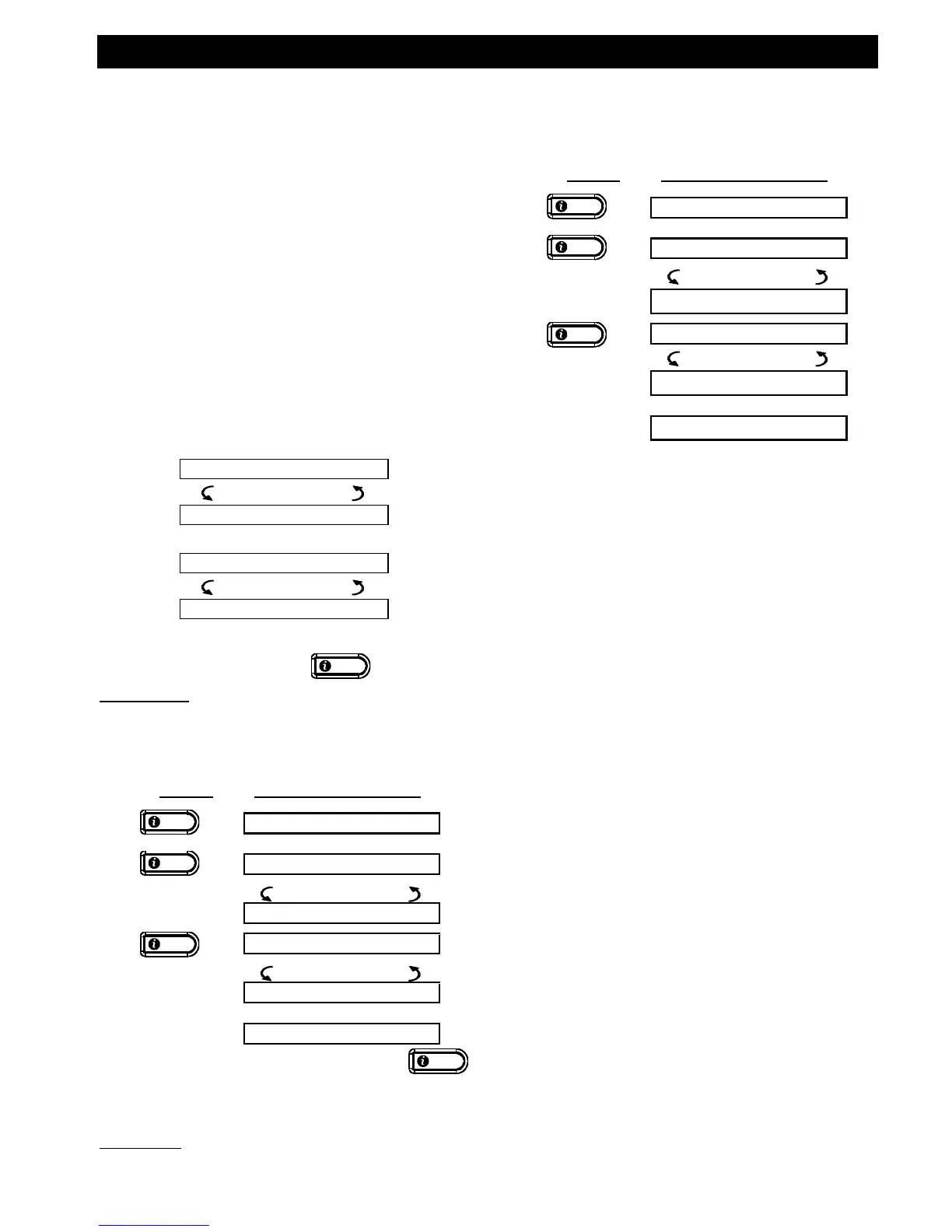
B. Investigating Alarm/Tamper Data
To review memory content, click
button.
EXAMPLE 1: An alarm was triggered because the
garage door - zone No. 12 – was opened but then
closed. In addition, the bedroom motion detector - zone
No. 7 - sent a “Tamper” message because its cover had
been removed.
In response to additional clicking of the
button, the display shows details of other events
retained in open tamper (if any), or reverts to its
initial state (see A above).
EXAMPLE 2: An alarm was triggered because the garage
door - zone No. 12 – was opened and remained open.
Remember! The memory indication and content are
cleared upon the next arming of the system.
Reviewing Trouble Information
A. Trouble Indications
If TRBL flashes in the display, the TROUBLE
indicator illuminates, and 3 beeps are sounded once
per minute, you will have to investigate the system in
order to find out the origin and type of trouble.
The LCD will display the device number(s) of the
trouble indication. The trouble types are as follows:
SENSOR TROUBLES
Inactivity - No radio signals have been received
from a particular sensor / wireless commander (if
its supervision feature has been enabled) during a
pre-defined period.
Low battery - The battery in a sensor, keyfob or
wireless commander is near the end of its useful life.
"Clean me" - The fire detector must be cleaned.
Gas trouble - Gas detector failure.
Siren AC failure - There is no power to the siren.
AC failure – There is no power to gas sensor
GSM TROUBLES (if used)
GSM line fail - GSM telephone line failure.
GSM net fail - GSM network failure.
RSSI low - The GSM received signal strength is low.
GSM communication fail - There is no
communication (RS-232 format) between
PowerMaxExpress and GSM unit.
SYSTEM TROUBLES
SYSTEM TROUBLES indicate the state of the entire
system and not a specific partition.
AC Supply Failure - There is no power and the
system is working on backup battery power.
System Jammed - A radio-frequency signal is
blocking communication channel of sensors and
control panel.

 Loading...