52
Repair instructions
6
Remove the press tool and mandrel.
(6x series): Install the cylinder head screws and
torque them. Please refer to “Cylinder head, installa-
tion” on pages 46 and 47.
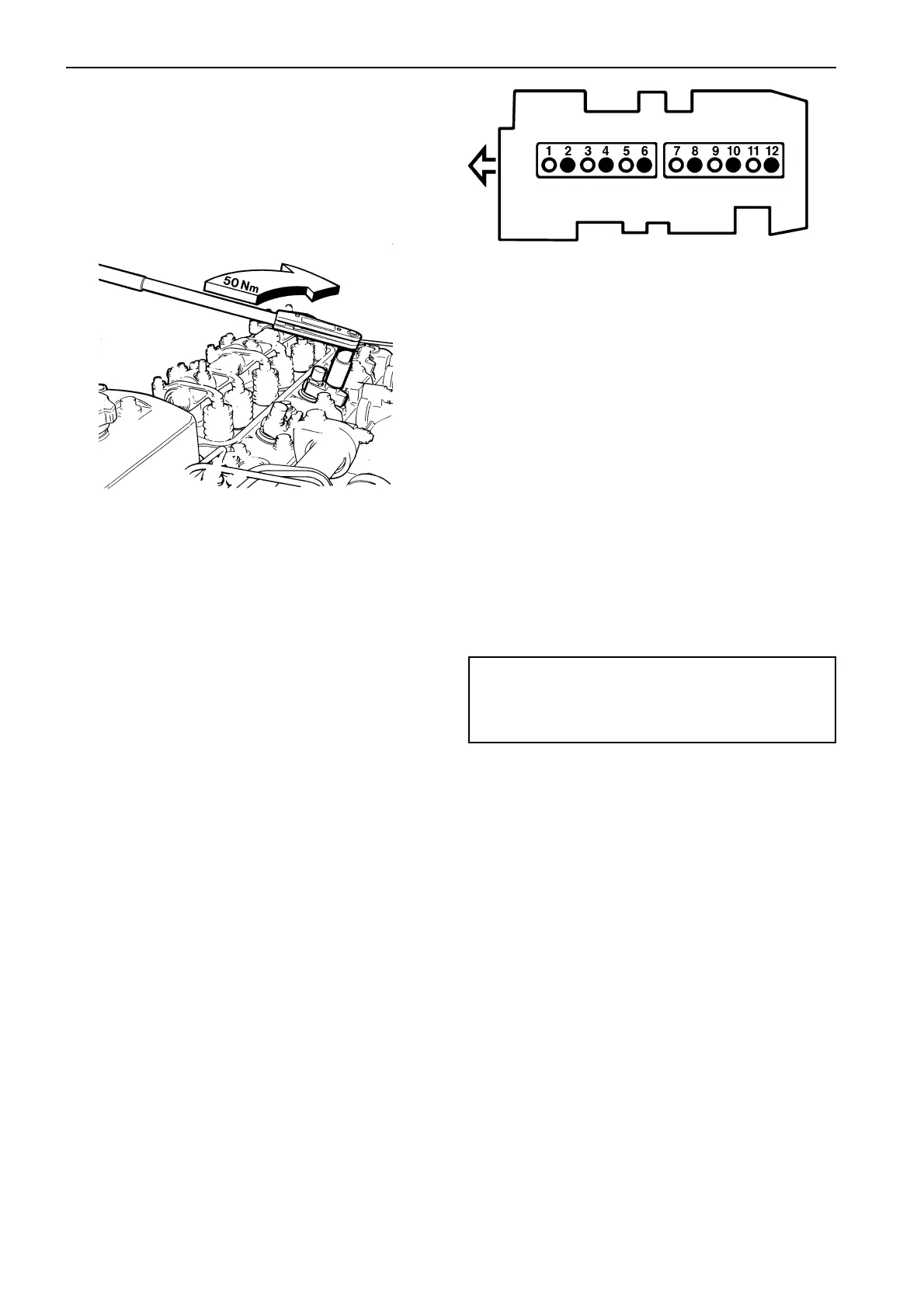
7
Install the injectors with dust covers and yokes.
Tightening torque is 50 Nm (5.0 kpm/37 lbf.ft). Install
the valve covers and oil leakage pipes.
8
Install the delivery pipes. Check that they have not
been skewed and tighten the nuts.
Tightening torque is 15–25 Nm (1.5–2.5 kpm/11–18
lbf.ft).
9
Fill up with coolant. Do a leakage check.
Valves, adjustment
NOTE! The clearance must never be checked when
the engine is running, it must be done with the engine
stationary, cold or at operating temperature.
Inlet ❍
Exhaust ●
Valve location and cylinder numbering
Valve clearance,
Inlet Exhaust
TAMD61, TAMD62,............. 0.40 mm 0.55 mm
TAMD71 (0.0157”) (0.0217”)
TAMD63, TAMD72,............. 0.50 mm 0.65 mm
TAMD73, TAMD74 (0.0197”) (0.0256”)
1
Remove the valve covers. When the valve clearance
is checked, the engine must only be cranked in its
normal direction of rotation. Cranking is done by turn-
ing the polygon hub on the crankshaft nose with a 21
mm ratchet spanner.
Firing sequence 1 5 3 6 2 4
Cylinder whose
rockers “tip” 6 2 4 1 5 3
2
Crank the engine in its normal direction of rotation un-
til the No. 1 piston is at TDC after the compression
stroke. This will cause the valves for cylinder No. 6 to
“tip”.
3
Crank the engine a third of a stroke in the correct di-
rection of rotation, and check the valve clearance for
piston No. 5. At the same time, the valves for cylinder
No. 2 will “tip”. Check the valve clearance for the
other cylinders in the firing sequence.
4
Clean the valve covers, replace damaged gaskets.
Tightening torque for nuts for the valve cover is
24 Nm (2.4 kpm/18 lbf.ft).
Test the engine and check that no oil leakage occurs.
 Loading...