75
Repair instructions
The surface finish (profile depth) of bearing surfaces
and fillets is 2 mm, medium surface deviation 5 mm.
This surface finish is achieved by buffing. Buffing is
done in the opposite direction of rotation to grinding.
l
Grinding must be done in a crankcase grinding
machine to an underdimension specified in the
“Technical Data” in the workshop manual.
l
It is very important that the fillet radii have the
correct dimensions:
R = 4.2–4.4 mm (6x series)
R = 3.4–3.6 mm (7x series)
And that they have the correct shape and sur-
face finish.
Measure the radius with a radius template. The
shape must correspond with the “Crankcase ra-
dii” on page 74. Grinding steps and sharp edges
must not occur, since these could cause the
crankshaft to break.
l
Special attention must be given to grinding the
centre main bearing journal, because of the
width of the locating bearing “A” in the “Crank-
shaft radii” illustration on page 74. For dimen-
sions, please refer to “Technical Data” in the
workshop manual.
NOTE! Round off sharp edges which might have
occurred by the oil duct holes when the bearing
journals were ground. Use a grinding bob or emery
cloth.
l
Clean the shaft carefully from grinding residue
and other contamination. Flush and clean the oil
ducts.
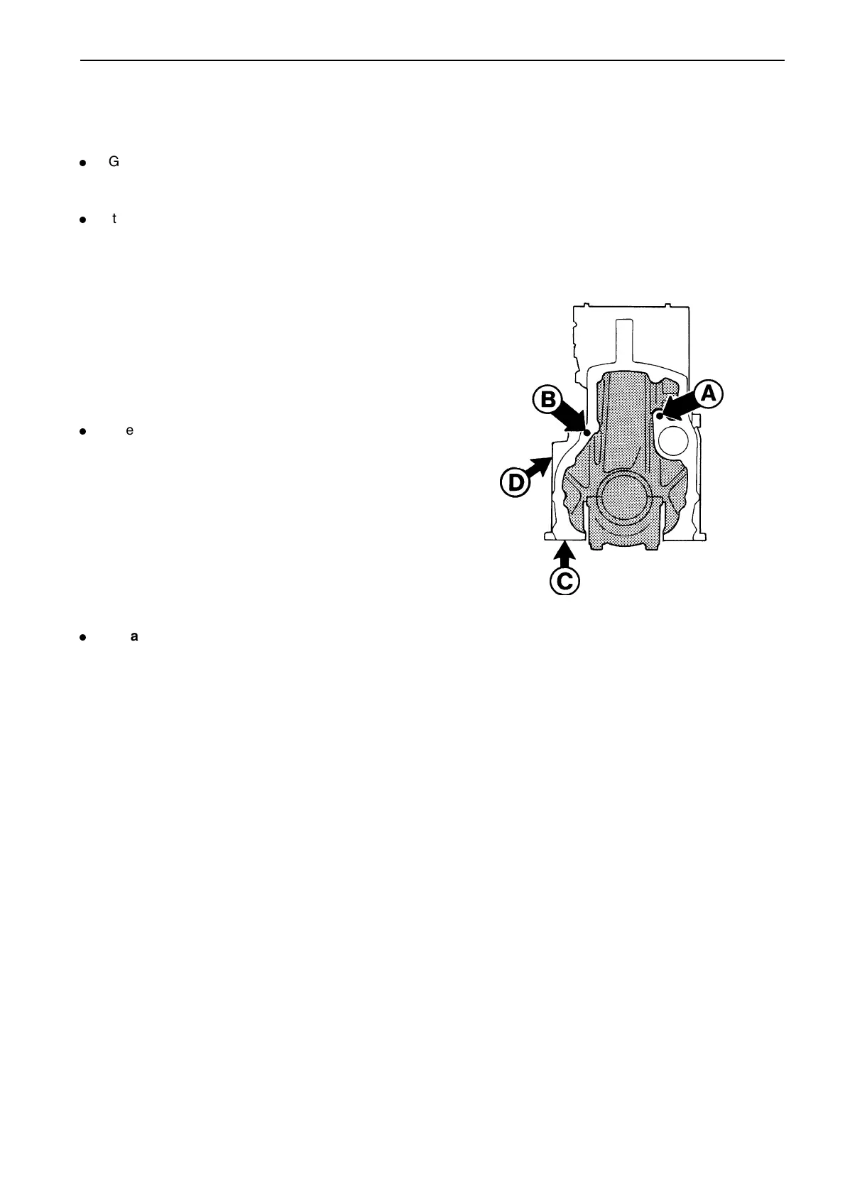
For piston cooling, a plug* (C) must be installed
underneath the engine block in addition to the
requisite nozzles, centred on the 5:th main bearing,
plus a plug (D) on the left-hand side of the engine
above the rear connection on the block for the flat oil
cooler.
* Note. The plug on early model TAMD61 and TAMD71 (By-pass
valve on TAMD62, TAMD72 and late model versions of TAMD61
and TAMD71).
Cylinder block, inspection
Clean the cylinder block carefully and check the
bearing journals, con rods and bearing caps for
damage.
Check that all oil ways are free from deposits and
that the block does not have any cracks. Small
cracks can be repaired by welding when hot. If
welding is done to the upper plane, the block must be
planed. If there are any major defects, the block must
be replaced.
To permit secure cleaning of the lengthwise oil ways,
spare part cylinder blocks are supplied without top
hat plugs.
NOTE! It is important that the plugs (part no. 95082-
3) are installed once cleaning has been carried out.
Distribution ducts (A) and (B) must always be
plugged at the front and rear of the engine.
Cylinder block seen from the rear
A Distribution duct – lubrication
B Distribution duct – piston cooling
C, D Duct for oil for piston cooling
Planing the cylinder block
If it is necessary to plane the cylinder block, this can
be done as long as the minimum dimensions noted
under Wear tolerances in “Technical Data” in the
workshop manual are considered. The upper cylinder
block plane on the TAMD63 and TAMD72 must not
be planed since the distance between the cylinder
crowns and valve heads could be too small. The
injector nozzle tips would also come too close.
NOTE! After the upper block plane has been ground,
the piston height above the cylinder block plane must
be checked. Max height: 0.55 mm (61 series) or 0.70
mm (71 series).
 Loading...