 Loading...
Do you have a question about the Welch Allyn 53000 and is the answer not in the manual?
| Brand | Welch Allyn |
|---|---|
| Model | 53000 |
| Category | Medical Equipment |
| Language | English |
Essential safety points for monitor usage and patient care, including placement, connections, and environmental factors.
Guidelines for handling sensitive electronic components to prevent damage from static electricity during servicing.
Explanation of documentation, certification, shipping, and connector symbols used in the manual.
Defines the manual's purpose for maintenance and corrective service of the Vital Signs Monitor 300 Series.
Details Welch Allyn's technical support, service options, warranty, and product return procedures.
Details various monitor configurations and outlines recommended service intervals and associated actions.
Describes the functional verification process and lists the necessary test equipment and accessories.
Step-by-step guide for testing monitor functions including System/Power, NIBP, SpO2, Temperature, Nurse Call, and Patient Isolation.
Provides a chart of common symptoms, causes, and remedies, plus requirements for module-level repair.
Overview of the service utility software for characterizing NIBP, managing logs, and updating monitor software.
Overview of disassembly, safety precautions, connector types, and screw torque specifications.
Instructions for disconnecting the battery and separating the monitor's front and rear chassis assemblies.
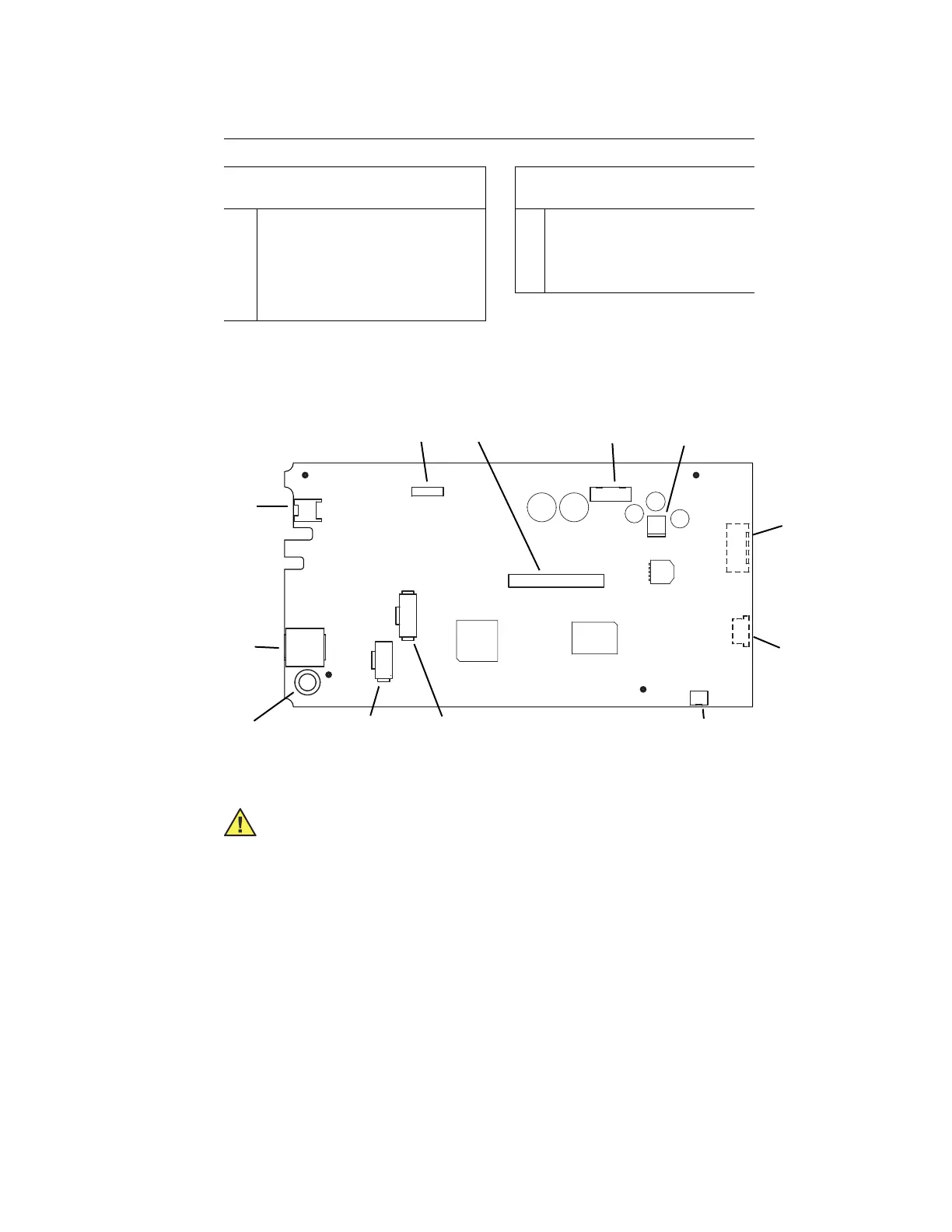
Detailed steps for removing the main board, NIBP, printer, temperature, and SpO2 modules.
Lists field-replaceable service parts for the front and rear cases, including part numbers and descriptions.
Details replacement parts for NIBP, Temperature, SpO2 (Nellcor/Masimo), and Printer options.
Lists various labels for overlays, error codes, safety, and essential special service tools and utilities.
Describes a clamp to prevent the DC power cord from disconnecting, available at no cost.