Appliance information
Greenstar i System
ErP
- 6 720 806 945 (2015/07)
15
Legend to figure 3:
[1] Mains supply
[2] Electrical connections
[3] HCM
[4] Ribbon cable to display screen
[5] NOT USED
[6] Circulating pump
[7] NOT USED
[8] Gas valve
[9] Flue overheat thermostat
[10] Fan
[11] Flow temperature sensor (NTC)
[12] Flame sense electrode
[13] Spark electrodes
[14] Overheat thermostat
[15] Spark generator
Resistance values
▶ Component resistance characteristics can be found
in section 8.2, page 70.
• Flow temperature NTC sensor
• DHW NTC sensor
• Flue overheat thermostat
• Overheat thermostat
• Outdoor weather compensation sensor
• Cylinder temperature sensor
• Gas valve
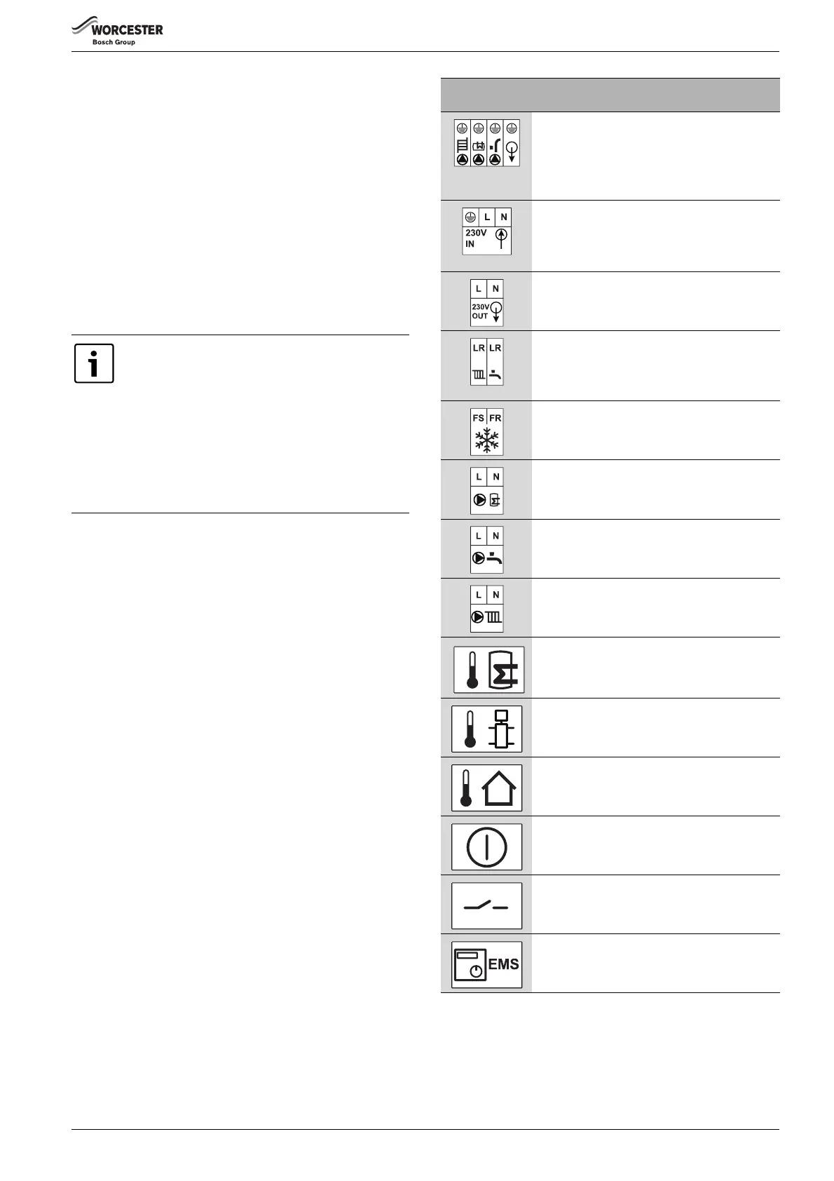
Connections/
symbol
Function
1)
Earth connections for:
• CH circulation pump (NOT USED)
• DHW charge pump (NOT USED)
• DHW circulation pump (NOT USED)
• 230V external controls
1) Green plug in connector pack found under installer connections cover.
230V supply to the appliance
• Earth input
• Neutral input
• Live input
230V feed to external controls
•Live output
• Neutral output
Switch live (Live Return) to appliance
• CH demand input
• DHW demand input (active when optional
integral diverter valve is fitted)
External frost thermostat
• FS output (Frost thermostat supply)
• FR input (Frost thermostat return)
DHW charge pump
(NOT USED)
DHW circulation pump
(NOT USED)
CH circulation pump
(NOT USED)
Cylinder sensor
• Cylinder sensor connection when using integral
diverter valve kit
Low Loss Header sensor
(NOT USED)
Outdoor weather compensation sensor
(used when accessary outdoor sensor is connected
when using integral diverter valve kit)
External cut off switch
(NOT USED)
Low voltage switch
(NOT USED)
2)
External control system with EMS bus control
(connection for Worcester intelligent wall mounted
controls when using integral diverter valve kit)
2) Orange plug in connector pack found under installer connections cover.
Table 9 Electrical connections
 Loading...