Service and spares
Greenstar i System
ErP
- 6 720 806 945 (2015/07)56
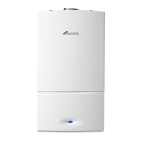
7.7.3 Draining the appliance
Many of the tasks in this section require that the appliance be isolated
and drained. This will be indicated in the manual if required.
▶ Connect a suitable hose firmly to the drain point and run the hose
outside to a suitable point or container.
▶ Turn the drain valve a ¼ turn anti-clockwise to open the drain. Turn
the valve firmly clockwise to close.
Fig. 72 Draining the appliance
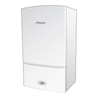
7.7.4 Fan assembly removal
Refer to figure 73
▶ Remove electrical connectors from fan.
▶ Remove wire clip from gas valve outlet.
▶ Pull the gas pipe free from the gas valve.
▶ Remove securing screw for the fan assembly.
▶ Lift the fan assembly out of the location slot.
Fig. 73 Fan assembly removal
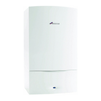
7.7.5 Air/gas manifold clamping plate removal
Before removing the air/gas manifold clamping plate, the following
actions will need to be carried out.
▶ Remove electrical connections from the electrode assembly,
( 7.7.6, Burner and electrode removal).
▶ Remove electrical connections from the primary sensor and remove
the primary sensor, ( 7.7.12, Primary sensor (CH NTC)).
▶ Remove electrical connections from the overheat thermostat,
( 7.7.13, Overheat thermostat).
Refer to figure 74.
▶ Remove earth connection from the air/gas manifold clamping plate.
▶ Undo the securing nut on the heat exchanger.
▶ Lift the air/gas manifold clamping plate up an out of the retaining
bracket.
▶ Refer to section 7.7.11 for refitting instructions.
Fig. 74 Air/gas manifold clamping plate removal
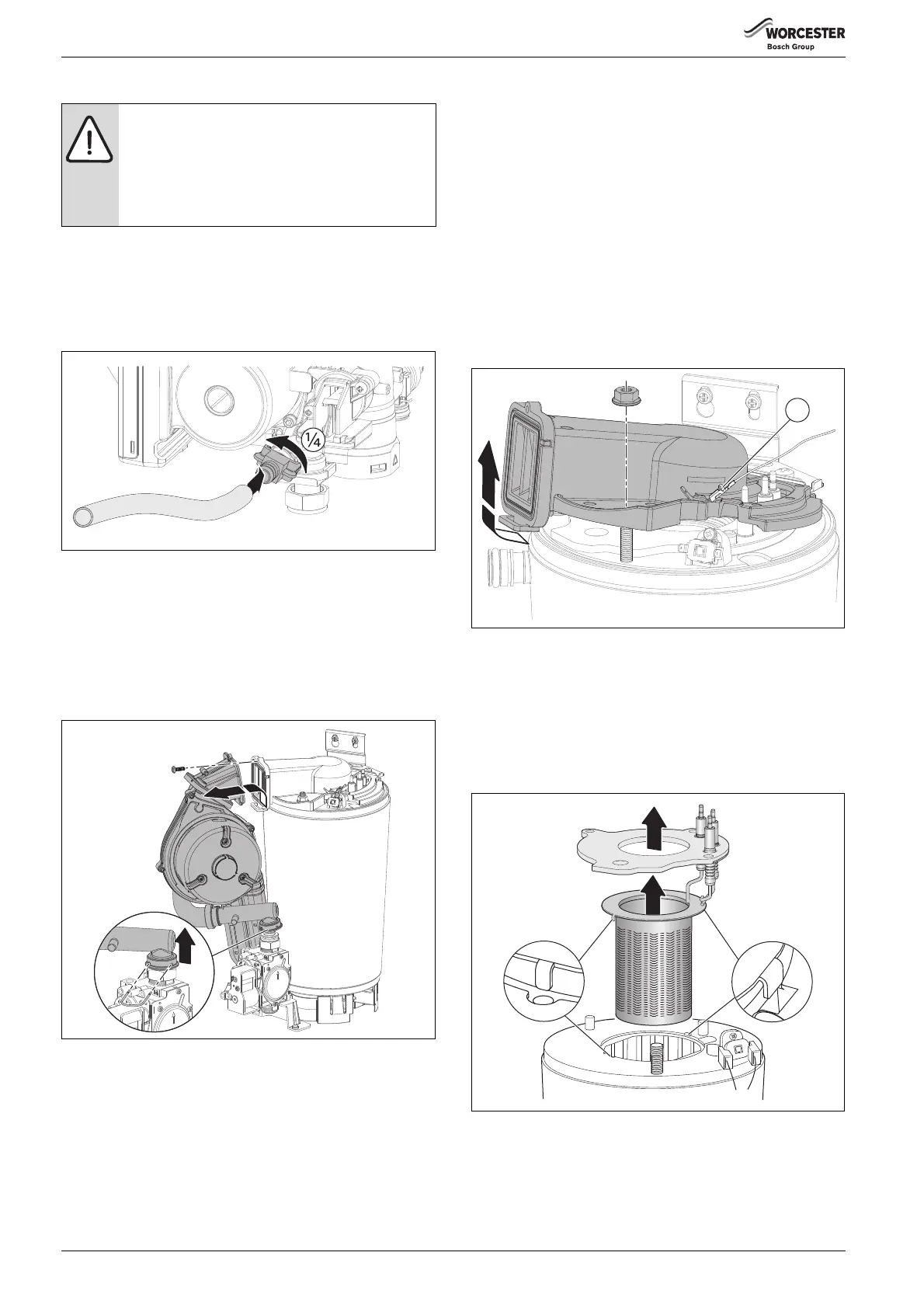
7.7.6 Burner and electrode removal
Refer to figure 75
▶ Remove electrical connections from the electrode assembly.
▶ Remove the air/gas manifold clamping plate as shown in figure 74.
▶ Remove spark/flame electrode assembly and seal from the top of the
heat exchanger.
▶ Remove burner.
Fig. 75 Burner removal
NOTICE: Risk of water damage to appliance or property!
Damage from disconnecting water pathways which may
have retained some water.
▶ Take care after draining appliance to protect
equipment/property from residual water content
within components.
6720806944-38.1Wo
 Loading...