Service and spares
Greenstar i System
ErP
- 6 720 806 945 (2015/07)
63
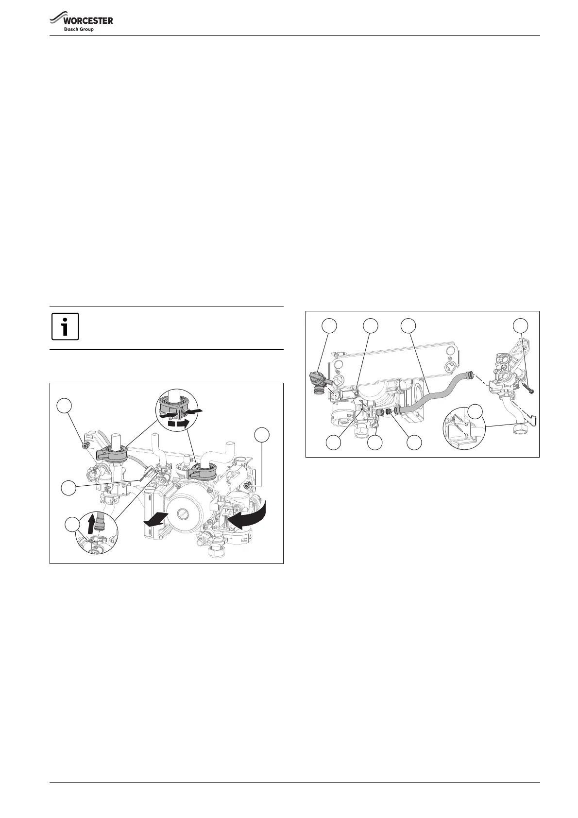
7.7.28 Hydraulic block removal
▶ Remove the Siphon assembly, refer to Siphon removal page 55.
Refer to figure 94
▶ Disconnect the electrical connections to the NTC sensor, turbine and
pump.
▶ Undo the nuts securing the copper water pipes to the manifold (there
is no need to remove the gas pipe).
▶ Remove the siphon.
▶ Release the spring clip [2] securing the expansion vessel pipe to the
plastic housing and remove the pipe.
▶ Release the spring clip [3] securing the pressure gauge sensing head
to the plastic housing and remove the sensing head.
▶ Release the locking devices that secure the two copper water pipes
leading to the combustion chamber by squeezing the two tabs
together and rotating anti-clockwise (viewed from above).
▶ Lower the pressure relief connector by pulling the lever forward and
down.
▶ Undo the two screws [1] securing the hydraulic block to the chassis
(located top left / top right of the housing).
▶ Lift the left hand side of the block slightly.
▶ Manoeuvre the block out, starting at the right hand side.
▶ Take care not to snag the harness.
▶ To refit, follow the above in reverse. Ensure any seals that have been
disturbed are renewed.
Fig. 94 Hydraulic block removal
7.7.29 CH pressure relief valve
Refer to figure 95
▶ Remove the hydraulic block from the appliance (See 7.7.28
Hydraulic block removal).
▶ Release the spring clip [2] from the Pressure Relief Valve housing.
▶ Withdraw the Pressure Release Valve [1] from its housing.
7.7.30 Bypass valve
Refer to figure 95
▶ Remove the hydraulic block from the appliance (See 7.7.28
Hydraulic block removal).
▶ Remove the spring clip [5] (on the left hand plastic housing to the
heat exchanger) of the copper bypass pipe [3].
▶ Undo the screw [4] securing the left hand plastic housing to the heat
exchanger.
▶ Move the housing to the left to free up the one end of the pipe.
▶ Remove the spring clip [8] (on the right hand plastic housing) of the
copper bypass pipe [3].
▶ Remove the pipe [3] from the right hand housing to reveal the bypass
valve [7]. Taking care not to lose the bypass pipe restrictor [6] from
inside the bypass pipe [3].
▶ Using a pair of pliers, pull out the bypass valve from the housing
▶ To refit, follow the above in reverse. Ensure any seals are renewed.
Fig. 95 PRV and bypass valve removal
The block will still contain an amount of water, which will
spill out if the block is tilted.
6720806945-04.1Wo
1 3
8
2 4
5
7 6
 Loading...