Installation
Greenstar i System
ErP
- 6 720 806 945 (2015/07)
33
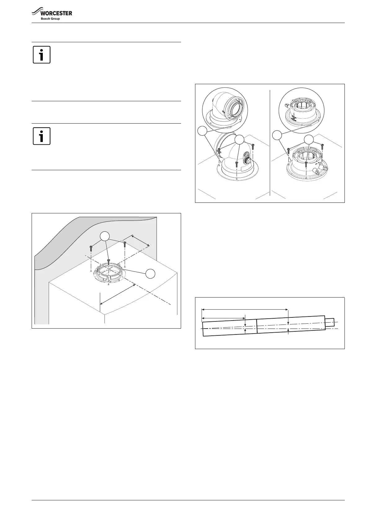
5.4 Flue turret/adaptor installation
The flue turret/adaptor for the appliance is secured using three retaining
screws (figure 35, item [1]) which come in position on the appliance.
Refer to figures 35 & 36.
▶ Remove the three inner flue tube retaining screws [1].
The inner tube will be held in place in the appliance.
▶ Check the appliance flue seal [2] is correctly seated and apply
silicone grease.
Fig. 35 Flue turret centre
[D] 133mm
[W] 200mm
▶ Align the flue turret/vertical adaptor to the appliance flue outlet with
flat facing [3] to the rear of the appliance.
The flue turret/adaptor should be pushed straight down, on to the
appliance.
▶ The three inner flue tube retaining screws [1] are, re-used for the flue
turret and replacement retaining screws [4] supplied with the
adaptor kit are used to secure turret/adaptor to the appliance.
Fig. 36 Flue turret/adaptor connection
Additional notes and reminders:
• Ensure that all cut lengths are square and free from burrs.
• Ensure that the flue and seals are not damaged.
• The flue is sealed when assembled correctly, the components are
pushed fully home and secured.
• The flue is set at an angle of 3° or 52mm per metre length.
• Support the flue at approximately one metre intervals and at a
change of direction, use suitable brackets and fittings
(flue bracket 100mm part number: 7 716 191 177,
flue brackets 100mm x 6 part number: 7 716 191 178,
flue bracket 125mm part number: 7 716 191 179)
Fig. 37 Slope for condensate disposal
If replacing a Greenstar i Junior (2005-2015) or a
Greenstar Si (2005-2013), the same rear exit flue hole
will align and can be re-used if deemed in a suitable
condition and in compliance with current legislation.
If replacing an existing side exit or a vertical flue, please
check the flue accessories available for the Greenstar i
before attempting to use the same hole.
To ease assembly of flue components, apply silicone
lubricant to sealing surfaces.
Refer to the manual supplied with the flue kit for
complete installation instructions.
For plume management effective lengths and the
effective flue lengths, refer to details in section 4.9.
6720806944-84.1Wo
W
al
l
W
D
1
2
6720806944-85.1Wo
3
1
3
4
6720644842-10.1Wo
2m
1m
52mm
104mm
 Loading...