Service and spares
Greenstar i System
ErP
- 6 720 806 945 (2015/07)
55
7.7 Replacement of parts
7.7.1 Component access
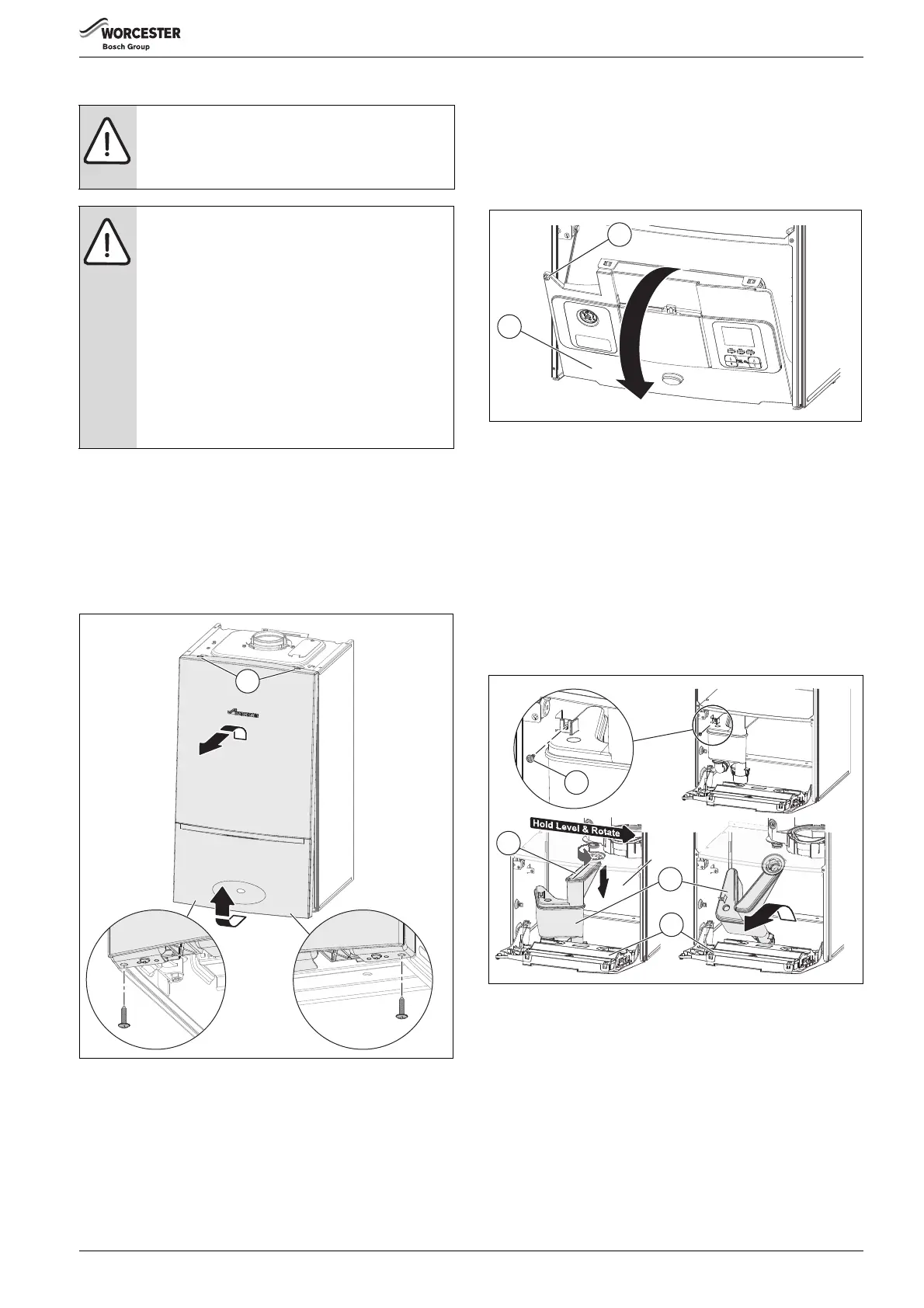
▶ Removing outer case
– Remove the bottom panel, pulling down the catch and sliding the
panel towards you.
– Remove the bottom two screws and pull the bottom of the panel
forward slightly.
– Lift front panel off the two locating lugs on the top of the
appliance [1].
Fig. 69 Remove outer case
7.7.2 Siphon removal replacement of parts
Access to the siphon
Refer to figure 70
▶ Release the screw securing the control panel [1].
▶ Hinge open the control panel [2] into service position.
Fig. 70 Access for removing siphon
Siphon removal
Refer to figure 71
▶ Place a suitable container under the siphon and remove the cap to
drain the siphon, replace the cap once drained.
▶ Remove the siphon securing screw [1].
▶ Rotate the siphon [2] level and to the right as far as possible to
release from the bayonet connection
▶ Pull the siphon [2] straight down to clear the connection.
▶ Tilt the siphon [2] to the front and remove over the control box
assembly [3].
– Lifting the control box assembly [3] up a little may ease the
removal of the siphon.
Fig. 71 Removing siphon
CAUTION: Mains supplies:
▶ Turn off the gas supply and isolate the mains supplies
before starting any work on the appliance and
observe all relevant safety precautions.
CAUTION: Component replacement:
▶ After replacement of a gas related component,
where a gasket or seal has been disturbed or
replaced, check for gas tightness using a gas sniffer/
analyser.
▶ On re-assembly check all affected seals for cracks,
hardness and deterioration.
If damaged or in any doubt the seal must be replaced.
▶Also after re-assembly, carry out the following
checks:
Fan pressure in section 7.4,
Flue gas analysis in section 6.5.9.
▶ Avoid trapping the primary sensor (CH NTC) clip.
6720806944-76.1Wo
1
 Loading...