Service and spares
Greenstar i System
ErP
- 6 720 806 945 (2015/07)62
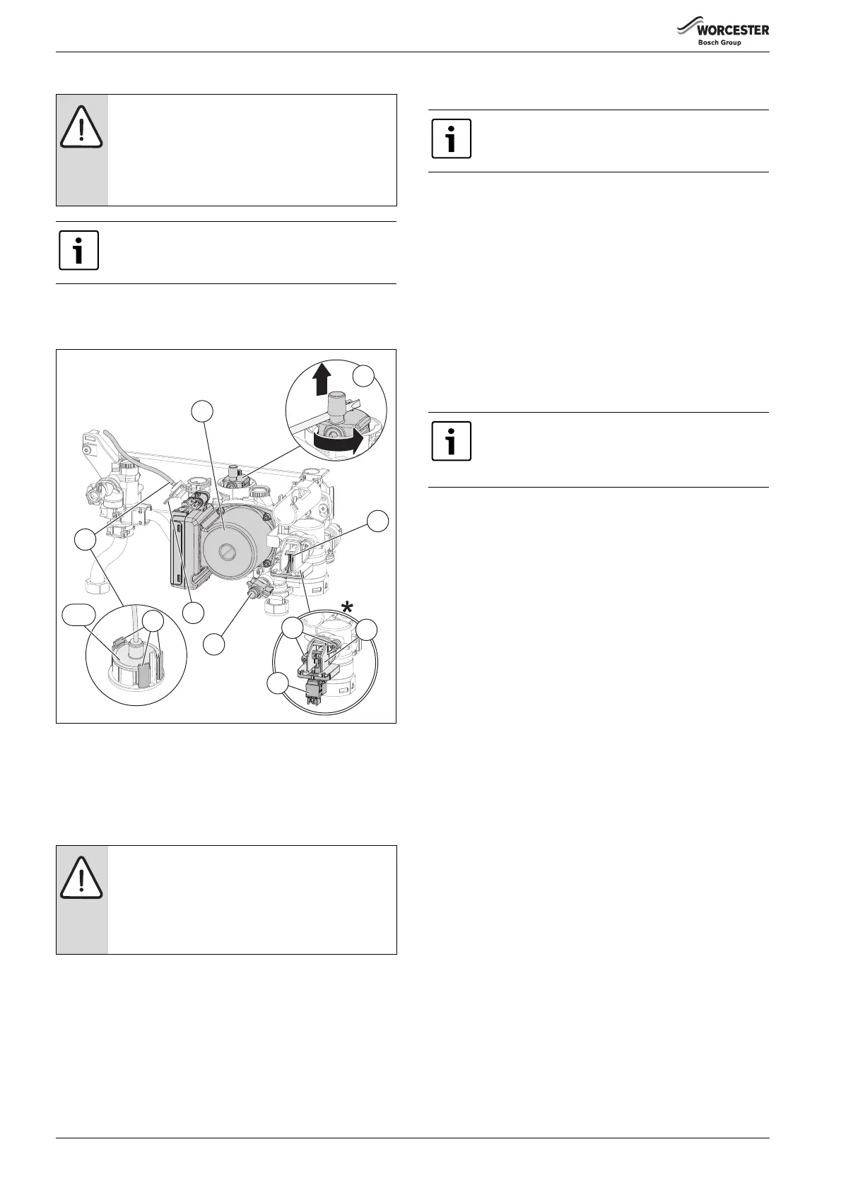
7.7.21 Hydraulic block components removal
When working on the hydraulic assembly, ensure that the appliance is
isolated and drained.
▶ Refer to section 7.7.3 for draining the appliance before proceeding.
Fig. 93 Hydraulic block
7.7.22 Auto air vent
Refer to figure 93
▶ Ensure the appliance is fully drained.
▶ Use a screwdriver or similar to rotate the air vent [2] anti-clockwise,
lift the air vent out of the housing and remove.
▶ To refit, follow the above in reverse.
7.7.23 Diverter valve motor (If optional integral diverter valve kit
fitted)
Refer to figure 93
▶ Enter service mode to ensure that the diverter valve is in mid
position.
▶ Disconnect the electrical connector from the diverter valve motor
and exit service mode.
▶ Remove the protective cover [6].
▶ Pull the diverter valve motor [9] from the housing.
▶ Re-fit the diverter valve motor, slide the motor into the housing.
▶ Ensure that “H” section of the motor actuator is fitted correctly into
valve body.
▶ Re-connect the electrical connection.
▶ Re-fit the protective cover.
7.7.24 Diverter valve
Refer to figure 93
▶ Disconnect the electrical connector from the diverter valve motor.
▶ Remove the protective cover [6].
▶ Pull the diverter valve motor [9] from the housing.
▶ Undo the two screws [8] from the diverter valve housing [7].
▶ Withdraw the diverter valve housing [7] and clean the valve chamber
if necessary.
▶ To re-fit, follow the above in reverse.
7.7.25 Drain tap
Refer to figure 93
▶ Rotate the drain tap [10] fully anti-clockwise and push in.
▶ Withdraw the drain tap from its housing.
7.7.26 Pump head
Refer to figure 93
▶ Disconnect the electrical connections from the pump.
▶ Remove the four screws securing the pump head.
▶ Pull the pump head [11] from the housing.
7.7.27 Pressure gauge
Refer to figure 93
▶ Prise the lugs [13] apart to release the gauge.
▶ Remove the gauge [14.1] taking care not to damage or kink the
capillary.
▶ Un-clip the capillary tube from the retainers on the left hand side of
the lower structure.
▶ Withdraw the spring clip [12] from the pressure sensing head
housing.
▶ Remove the pressure sensing head [14] and pressure gauge
capillary from the housing.
▶ To re-fit follow the above in reverse. DO NOT omit the washer from
the capillary when fitting a replacement gauge.
NOTICE: Risk of water damage to appliance or property!
Damage from disconnecting water pathways which may
have retained some water.
▶ Take care after draining appliance to protect
equipment/property from residual water content
within components.
Ensure any seals that have been disturbed are renewed.
NOTICE:
▶ The “O” ring must be fitted to the Auto air vent and
NOT the hydraulic block otherwise the Auto air vent
will be difficult to fit.
▶ Apply silicone lubricant to the “O” ring to ease
assembly.
6720806945-16.1Wo
1
8
2
7
3
5
6
4
10
9
10.1
The appliance does not have to be drained to remove the
diverter valve motor.
Ensure the appliance is fulled drained before removing
the diverter valve.
To ease assembly of components, apply silicone
lubricant to sealing surfaces.
 Loading...