Pre-installation
Greenstar i System
ErP
- 6 720 806 945 (2015/07)
23
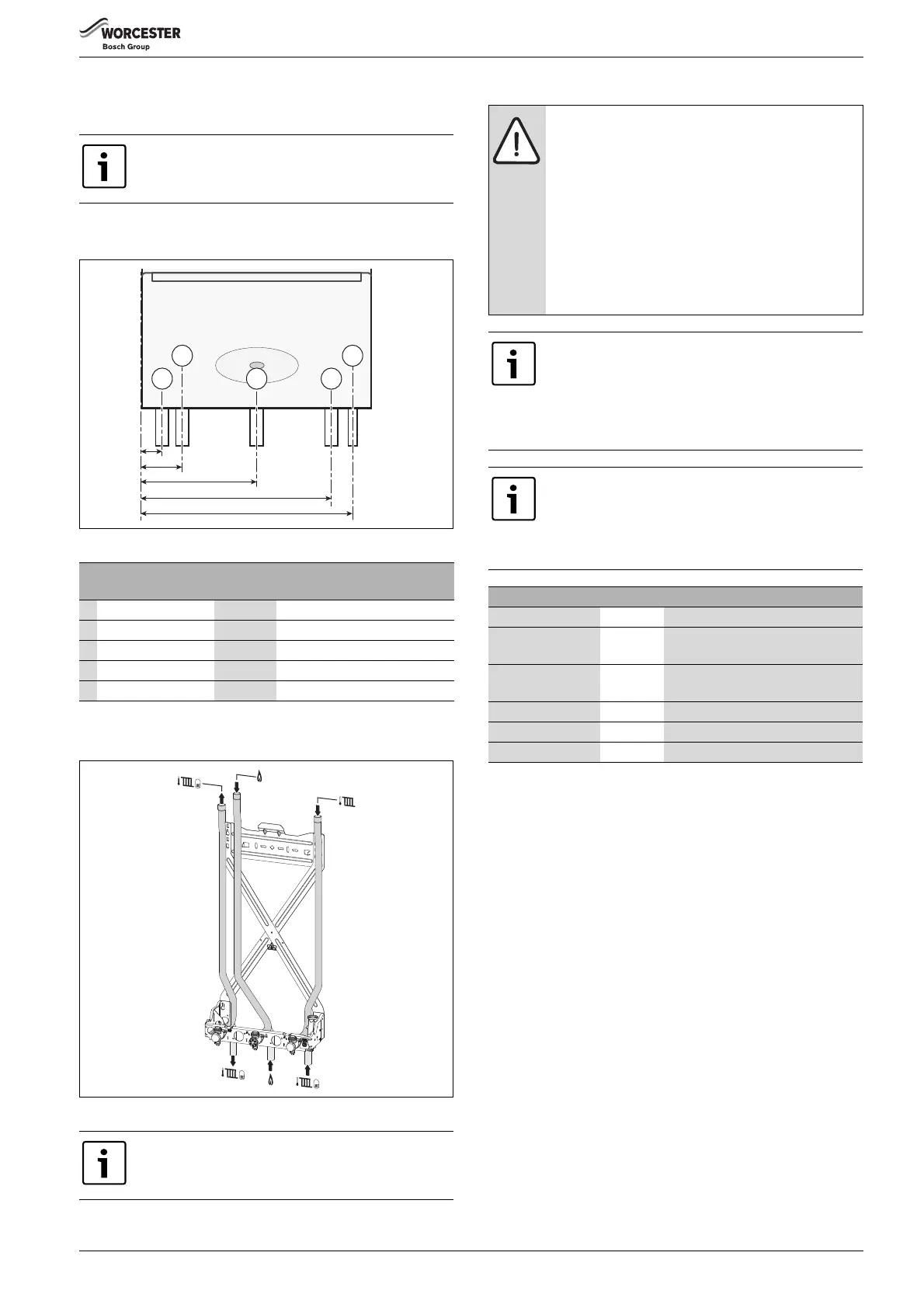
4.8 Plumbing manifold
4.8.1 Connections
• For further ease of fitting, an optional Vertical Pre-piping Assembly
kit is available, comprising four pre-formed copper water pipes.
Fig. 18 Pipe dimensions external diverter valve/s and controls
Use the fittings supplied in the Hardware literature pack.
Fig. 19 Pipes within wall frame example
4.9 Flue options
Further guidance on pipe routing can be found printed
on the appliance template (supplied with the appliance).
# Function
From left
case edge
Diameter of pipe
1Condensate 38mm 22mm rubber push fit connector
2CH Flow 70mm 22mm compression fitting
3Gas 200mm 22mm compression fittings
4CH Return 330mm 22mm compression fitting
5 Pressure Relief Valve 364mm 15mm (fittings not supplied)
Table 14 Key to figure 18
Optional integral diverter valve kit
▶ Details for pipe configuration can be found in the kit
Installation Instructions.
CAUTION: Non accessible flue systems:
▶ Where a flue system is not going to be accessible,
provision must be made for service and inspection.
▶ Voids containing concealed flues must have at least
one inspection hatch no less than 300mm square.
▶ Flue joints within the void must not be more than 1.5
metres from the edge of the inspection hatch.
▶ Inspection hatches should be located at changes of
direction.
▶ If this is not possible, bends should be viewable from
both directions.
Refer to the manual supplied with the flue kit for
complete installation instructions.
Plume management kits are available for the 60/100
horizontal flue system.
▶ Only use the approved Worcester Condensfit II flue
system with this appliance.
Effective flue lengths:
▶ Each 90° bend used is equivalent to 2 metres of
straight flue.
▶ Each 45° bend used is equivalent to 1 metres of
straight flue.
Part number Flue Description
7 716 191 082 60/100 Telescopic horizontal flue assembly
7 716 191 171 60/100 Longer telescopic horizontal flue
assembly
7 733 600 048 60/100 Horizontal high level telescopic flue
kit
7 719 003 702 80/125 Telescopic horizontal flue assembly
7 719 002 430 60/100 Vertical flue assembly
7 719 002 431 80/125 Vertical flue assembly
Table 15 Flue kit part numbers
 Loading...