MEMORY
WRITE
PROTECTION
LOCKS
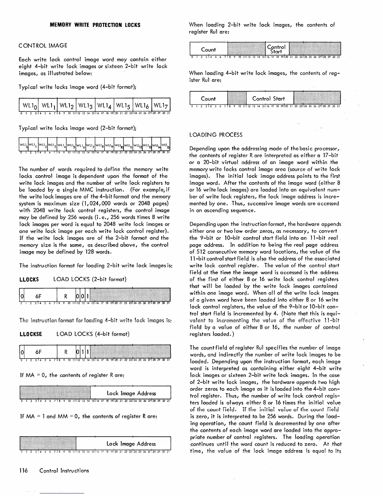
CONTROL IMAGE
Each write lock control image word may contain
either
eight
4-bit
write lock images or sixteen
2-bit
write lock
images, as illustrated below:
Typi cal write locks image word {4-bit format};
Typical write locks image word
{2-bit
format};
The number
of
words required to
define
the
memory write
locks control image
is
dependent
upon
the
format
of
the
write lock images and the number
of
write lock registers to
be loaded by a single
MMC instruction.
{For
example, if
the
write lock images
are
of
the
4-bit
format and
the
memory
system
is
maximum
size
(1,024,000
words
or
2048 pages)
with
2048 write lock control registers, the control image
may
be
defined
by 256 words
(i.
e.,
256 words times 8 write
lock images
per
word
is
equal
to 2048 write lock images or
one
write lock image
per
each
write lock control register).
If
the
write lock images
are
of
the
2-bit
format
and
the
memory
size
is
the same, as described
above,
the
control
image may be
defined
by 128 words.
The instruction format for loading
2-bit
write lock images
is:
LLOCKS
LOAD LOCKS
(2-bit
format)
The instruction format for loading
4-bit
v:rite
!eck
imcges
is:
LLOCKSE
LOAD LOCKS
(4-bit
format)
If
MA
=
0,
the
contents
of
register
Rare:
If
MA
= 1 and
MM
=0,
the contents
of
register
Rare:
lock
lmag~
Address
I , ,
116 Control Instructions
When loading
2-bit
write lock images, the contents
of
register
Ru1
are:
When loading
4-bit
write lock images, the contents of
reg-
ister
Ru1
are:
LOADING
PROCESS
Depending upon
the
addressing mode of the basi c processor,
the contents
of
register R
are
interpreted as
either
a
17-bit
or a
20-bit
virtual address
of
an image word within the
memory write locks control image
area
(source
of
write lock
images). The initial lock image address points to the first
image word.
After
the
contents
of
the image word
(either
8
or
16
write lock images)
are
loaded into an
equivalent
num-
ber
of
write lock registers, the lock image address
is
incre-
mented by
one.
Thus, successive image words
are
accessed
in an ascending
sequence.
Depending upon
the
instruction format, the hardware appends
either
one
or two low order zeros, as necessary,
to
convert
the
9-bit
or
10-bit
control start field into
an
11-bit
real _
page address.
In
addition
to being the real page address
of
512 consecutive memory word
locations,
the
value
of
the
ll-bit
control start field
is
also
the
address of the
asso~iated
write lock control register. The
value
of the control start
field
at
the time
the
image word
is
accessed
is
the
address
of
the
first
of
either
8
or
16
write lock control registers
that
will be loaded by the write lock images contained
within one image word. When
all
of
the
write lock images
of a given word have been loaded into
either
8
or
16
write
lock control registers,
the
val ue
of
the
9-bit
or
10-bit
con-
trol start field
is
incremented by
4.
(Note
that
this
is
equi-
valent
to incrementing the \-'c!ue
of
the
effective
l1-bit
field by a
value
of
either
8 or 16, the number of control
registers
loaded.)
The count field
of
register
Ru1
specifies the number
of
image
words, and
indirectly
the
number
of
write lock images to be
loaded.
Depending upon the instruction format,
each
image
word
is
interpreted
as containing
either
eight
4-bit
write
lock images or sixteen
2-bit
write lock images.
In
the case
of
2-bit
write lock images,
the
hardware appends two high
order zeros to
each
image as
it
is
loaded into the
4-bit
con-
trol register. Thus,
the
number
of
write lock control
regis-
ters loaded
is
always
either
8 or
16
times the initial
value
of the count field.
If
the initial valut::
of
-the
count field
is
zero,
it
is
interpreted
to be 256 words. During the
load-
ing
operation,
the
count field
is
decremented by
one
after
the
contents
of
each
image word
are
loaded into the
appro-
priate
number
of
control registers. The loading operation
continues until
the
word count
is
reduced to
zero.
At
that
time,
the
value
of the lock image address
is
equal to its
 Loading...