4. Each
unit-record
controller (internal or
external)
requires one
I/O
subchannel per
each
unit record
de-
vice
attached,
up to a maximum
of
eight.
5. The maximum number
of
internal
device
controllers
within an
MIOP
is
eight
(where a
unit-record
device
controller
is
equivalent
to
one,
regardless
of
the
number
of
assigned subchannels).
6.
Any
I/O
subchannel not assigned to an internal
device
controller may be assigned to an
external
device
con-
troller. Thus,
if
an MIOP has no internal
device
con-
troller,
all
16
I/O
subchannels may be assigned to
external
device
controllers.
ROTATING
MEMORY
PROCESSOR
(RMP)
Each
RMP
is
a speci_al purpose,
single-channel
lOP designed
to
enhance
high-speed
data
transfers between main memory
and
anyone
of up to
eight
disk units. Functionally, an
RMP
is
comparable to an MIOP,
except:
(1)
at
any
given
time,
only
one disk unit may be
selected
for a
data
transfer
operation,
.
(2)
data
transfer
rate
of
disk units
are
generally
higher than
data
transfer rates
of
I/O
devices
attached
to
an
MIOP, and
(3)
the
device
controller
function
is
per-
formed by the
RMP,
hence
disk units
are
connected
directly
to the
RMP
rather
than
via
a
device
controller. (Note:
Although only one disk
unit
may be
actively
transferdng
data
at
any
given time, the
other
units may be
active
in
performing control functions,
e.
g.,
seeking).
iNPUT
jOUTPUT
PKOCESSOR
liOfij
FUNUAMENTAlS
This section contains general information, programming
con-
cepts, and definition
of
terms pertaining to
I/O
operations
performed by
Input/Output
Processors (i.
e.,
MIOP and
RMP
systems).
The
large
variety
of
I/O
devices
which may
be used with
these
lOPs precludes a
detailed
or
exhaustive
description of features which
are
unique
to
each
device.
Likewise, a general
reference
"Refer
to
an
appropriate
Xerox peripheral
reference
manual" is made
rather
than
citing
specific manuals.
Within this manual, the following terminology is used to
differentiate
the
hierarchy
of
control during an
I/o
opera-
tion: The
BP
executes
instructions, the lOPs
execute
com-
mands, and the
device
controller/device
execute
orders.
COMMAND
LIST
Each
I/O
operation performed by
an
lOP
must be
defined
by a command list. The
characteristics
and requirements
of
a command list
are
as follows:
1.
It is normally
created
by a BP-executed program
prior to the time
that
the defined
I/o
operation
is
initiated.
It
must reside in main memory when the
I/o
operation
is
initiated
and subsequently
executed.
2. Depending upon various programming considerations,
the command list may be
contained
within one or more
areas
of
memory and
each
area
may be comprised
of
one or more
I/O
command doublewords (IOCDs).
3. Command list
continuity
between
10CDs
relating
to the
same logical record or to
the
same logical file may be
specified
(see
"Data
Chain Flag" and "Command Chain
Flag
ll
under
II
Operationa
I
10CDs").
Command list
continuity
between portions
of
a command list
located
in
different
areas
of
main memory may be accomplished
by
including
a control
10CD
within
the
command list
(see "Transfer in Channel
II
under "Control
10CDs").
4. Each
10CD
is
comprised
of
two words in contiguous
memory word locations.
The
first word must be stored
in an
even
memory word location and the second word
must be stored in the
next
consecutive
(odd) memory
word
location.
Each IOCD is
either
an
operational
IOCD or a control IOCD and
contains
coded
parameters
to define
either
a complete
I/Ooperation
or an integral
portion
of
an
I/Ooperation.
(See
"Operational
IOCD"
and IIControl IOCD" for further
detai
Is. )
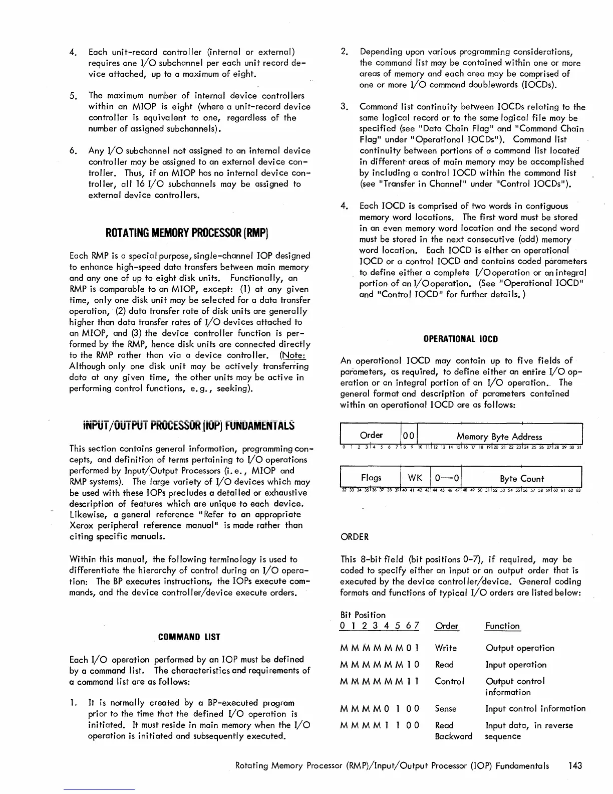
OPERATIONAL
lOCO
An
operational
IOCD may
contain
up to five fields
of
parameters, as
required,
to
define
either
an
entire
I/o
op-
eration
or
an integral portion
of
an
I/o
operation._ The
general format and description
of
parameters
contained
within
an
operational
10CD
are
as follows:
ORDER
This
8-bit
field
(bit positions
0-7),
if
required, may be
coded to specify
either
an
input
or
an
output
order
that
is
executed
by the
device
controller/device.
General
coding
formats and functions
of
typical
I/o
orders
are
listed below:
Bit Position
o 1 2 3 4 5 6 7
Order
Function
MMMMMM01
MMMMMM10
MMMMMM11
MMMMO
MMMM1
00
00
Write
Read
Control
Output
operation
Input
operation
Output
control
information
Sense Input control information
Read
Input
data,
in reverse
Backward sequence
Rotating Memory Processor
(RMP)/Input/Output
Processor (lOP) Fundamentals 143

 Loading...