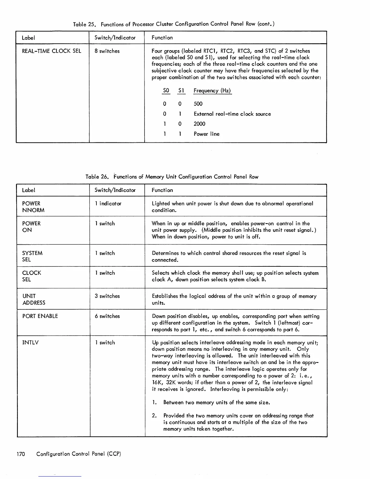
Table
25.
Functions
of
Processor Cluster Configuration Control Panel
Row
(cont.)
Label
I
Swi
tch/Indi
cator
Function
REAL-
TIME
CLOCK
SEL
8 switches
Four groups
(labeled
RTC1, RTC2,
RTC3,
and
STC)
of 2 switches
each
(labeled
SO
and S 1), used for
selecting
the
real-time
clock
frequencies;
each
of
the
three
real-time
clock
counters
and
the
one
subjective
clock
counter
may
have
their
frequencies
selected
by
the
proper combination of the two switches
associated
with
each
counter:
SO
Sl
Frequency (Hz)
-
-
0 0 500
0
1 External
real-time
clock
source
1 0 2000
1 1
Power line
Table 26. Functions of Memory Unit Configuration Control Panel
Row
Label
POWER
NNORM
POWER
ON
SYSTEM
SEL
CLOCK
SEL
UNIT
ADDRESS
PORT
ENABLE
INTLV
Switch/Indicator
1
indicator
1 switch
1 switch
1 switch
3 switches
6 switches
1 switch
170 Configuration Control Panel (CCP)
Function
Lighted when unit power is shut down due
to
abnormal operational
condition.
When in up or middle position,
enables
power-on
control in
the
unit
power supply. (Middle position inhibits
the
unit
reset
signal.)
When in down position, power
to
unit is off.
Determines
to
which
central
shared resources
the
reset signal is
connected.
Selects
which
clock
the
memory shall use; up position
selects
system
clock
A, down position
selects
system
clock
B.
Establishes
the
logical address of
the
unit
within a group of memory
units.
Down position disables, up
enables,
corresponding port when setting
up
different
configuration
in
the
system. Switch 1 (leftmost)
cor-
responds
to
port 1,
etc.,
and
swi
tch 6 corresponds
to
port 6.
Up
position
selects
interleave
addressing mode in
each
memory unit;
down position means no
interleaving
in
any
memory unit.
Only
two-way
interleaving
is
allowed.
The unit
interleaved
with this
memory unit must
have
its
interleave
switch on
and
be in
the
appro-
priate
addressing
range.
The
interleave
logic
operates
only for
memory units with a number corresponding
to
a power of 2:
i.
e.
,
16K, 32K words;
if
other
than a power
of
2,
the
interleave
signal
it
receives
is
ignored.
Interleaving
is
permissible only:
1.
Between two memory units of
the
same
size.
2.
Provided
the
two memory units
cover
an
addressing range
that
is continuous
and
starts
at
a
multiple
of the
size
of
the
two
memory units
taken
together.
 Loading...