Label
POWER
NNORM
POWER
ON
SYSTEM
SEL
CLOCK
SEL
PROCESSOR
ADDRESS
BP
ENABLE
MIOP
ENABLE
DIO
ENABLE
ALTSEL
FSELA
FSELBO/FSELBl
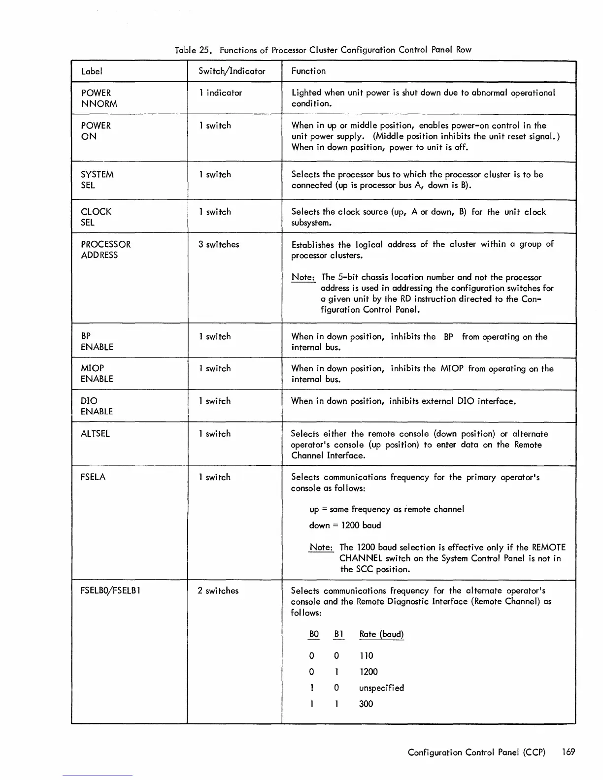
Table
25.
Functions
of
Processor Cluster Configuration Control Panel
Row
Switch/Indicator
1
indicator
1 switch
1 switch
1 switch
3 switches
1 switch
1 switch
1 switch
1 switch
1 switch
2 switches
Function
Lighted when unit power is shut down
due
to
abnormal operational
condition.
When in
up
or middle position,
enables
power-on
control in the
unit power supply. (Middle position inhibits
the
unit
reset
signal.)
When in down position, power
to
unit is off.
Selects
the
processor bus
to
which
the
processor
cluster
is
to
be
connected
(up is processor bus A, down is
B).
Selects
the
clock
source (up, A or down,
B)
for the unit
clock
subsystem.
Establishes
the
logical address of
the
cluster
within
a group
of
proc essor clusters.
Note:
The
5-bit
chassis
location
number
and
not
the
processor
address is used in addressing
the
configuration
switches for
a
given
unit by
the
RD
instruction
directed
to
the
Con-
figuration Control Panel.
When in down position, inhibits
the
BP
from operating on
the
internal bus.
When in down position, inhibits
the
MIOP from operating on
the
i nterna I bus.
When in down position, inhibits
external
DIO
interface.
Selects
either
the
remote console (down position) or
alternate
operator1s console (up position)
to
enter
data
on
the
Remote
Channel
Interface.
Selects
communications frequency for
the
primary operator1s
console
as follows:
up
= same frequency as remote
channel
down = 1200 baud
Note:
The 1200 baud
selection
is
effective
only
if
the
REMOTE
CHANNEL switch on
the
System Control Panel is not in
the
SCC posi ti on.
Selects
communications frequency for
the
alternate
operator1s
console
and
the
Remote Diagnostic
Interface
(Remote Channel) as
follows:
BO
B1
Rate (baud)
- -
0
0
110
0
1 1200
1
0
unspecified
1 1 300
Configuration Control Panel (CCP) 169
 Loading...