SP605 Hardware User Guide www.xilinx.com 41
UG526 (v1.9) February 14, 2019
Detailed Description
15. Status LEDs
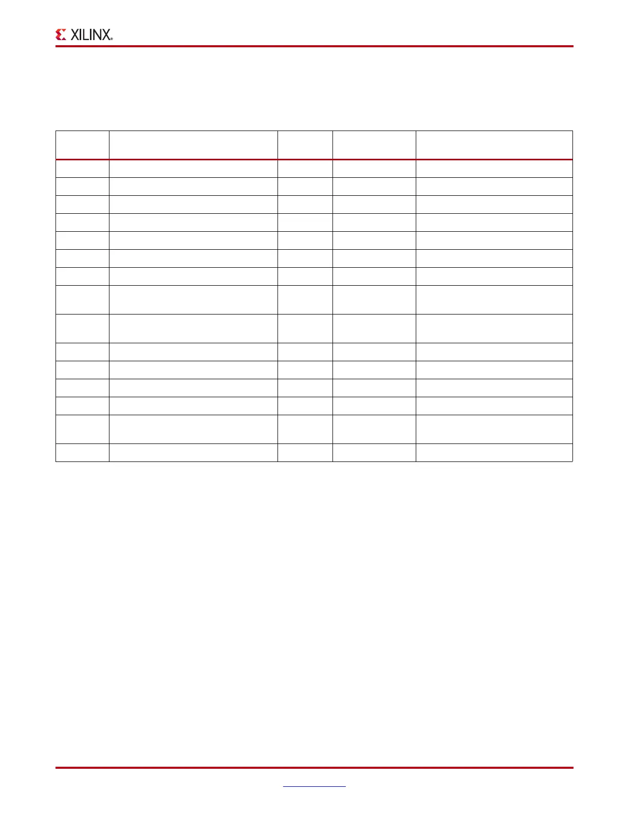
Table 1-21 defines the status LEDs.
Table 1-21: Status LEDs
Reference
Designator
Signal Name Color Label Description
DS1 FMC_PWR_GOOD_FLASH_RST_B Green FMC PWR GD FMC Power Good
DS2 FPGA_DONE Green DONE FPGA DONE
DS3 GPIO_LED_0 Green GPIO_LED_0
DS4 GPIO_LED_1 Green GPIO_LED_1
DS5 GPIO_LED_2 Green GPIO_LED_2
DS6 GPIO_LED_3 Green GPIO_LED_3
DS7 FPGA_AWAKE Green FPGA AWAKE
DS8 SYSACE_STAT_LED Green
System ACE CF
Status LED
System ACE CF Status
DS9
TI_PWRGOOD (AND)
MGT_TI_PWRGOOD
Green POWER GOOD
TI_CORE_PWR+TI_MGT_PWR
GOOD
DS10 LED_RED / LED_GRN Red/Green STATUS USB JTAG Controller Status
DS14 VCC12_P Green 12V 12V Power On
DS15 (U11.9 PGOOD PIN) Green DDR3 PWR GD DDR3 1.5V Power On
DS17 FPGA_INIT_B Red INIT FPGA INIT
DS18 SYSACE_ERR_LED Red
System ACE CF
Error LED
System ACE CF Error
DS19 MGT_POWERGOOD Green MGT_AVCC GD MGT_AVCC Power On

 Loading...


