SP605 Hardware User Guide www.xilinx.com 43
UG526 (v1.9) February 14, 2019
Detailed Description
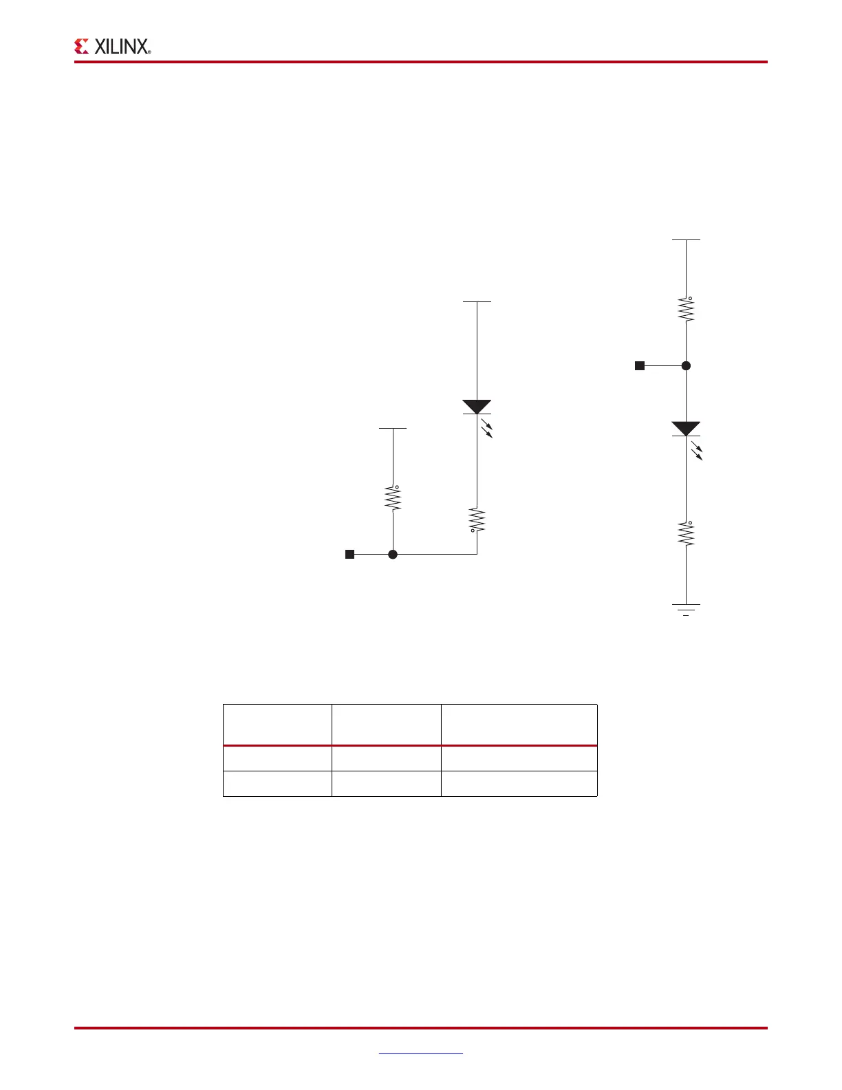
FPGA INIT and DONE LEDs
The typical Xilinx FPGA power up and configuration status LEDs are present on the SP605.
The red INIT LED DS17 comes on momentarily after the FPGA powers up and during its
internal power-on process. The DONE LED DS2 comes on after the FPGA programming
bitstream has been downloaded and the FPGA successfully configured.
X-Ref Target - Figure 1-1 4
Figure 1-14: FPGA INIT and DONE LEDs
Table 1-22: FPGA INIT and DONE LED Connections
U1 FPGA Pin
Schematic Net
Name
Controlled LED
Y4 FPGA_INIT_B DS17 INIT, Red
AB21 FPGA_DONE DS2 DONE, Green
VCC2V5
VCC2V5
VCC2V5
INIT_B = 0, LED: ON
INIT_B = 1, LED: OFF
1
2
R70
27.4
1/16W
1%
1
2
R169
332
1/16W
1%
2
1
DS2
LED-GRN-SMT
1
2
R69
75.0
1%
2
1
DS17
LED-RED-SMT
FPGA_INIT_B
2
1
5%
1/16W
4.7K
R19
FPGA_DONE
UG526_14 _092409

 Loading...


