ZCU104 Board User Guide 14
UG1267 (v1.1) October 9, 2018 www.xilinx.com
Chapter 2: Board Setup and Configuration
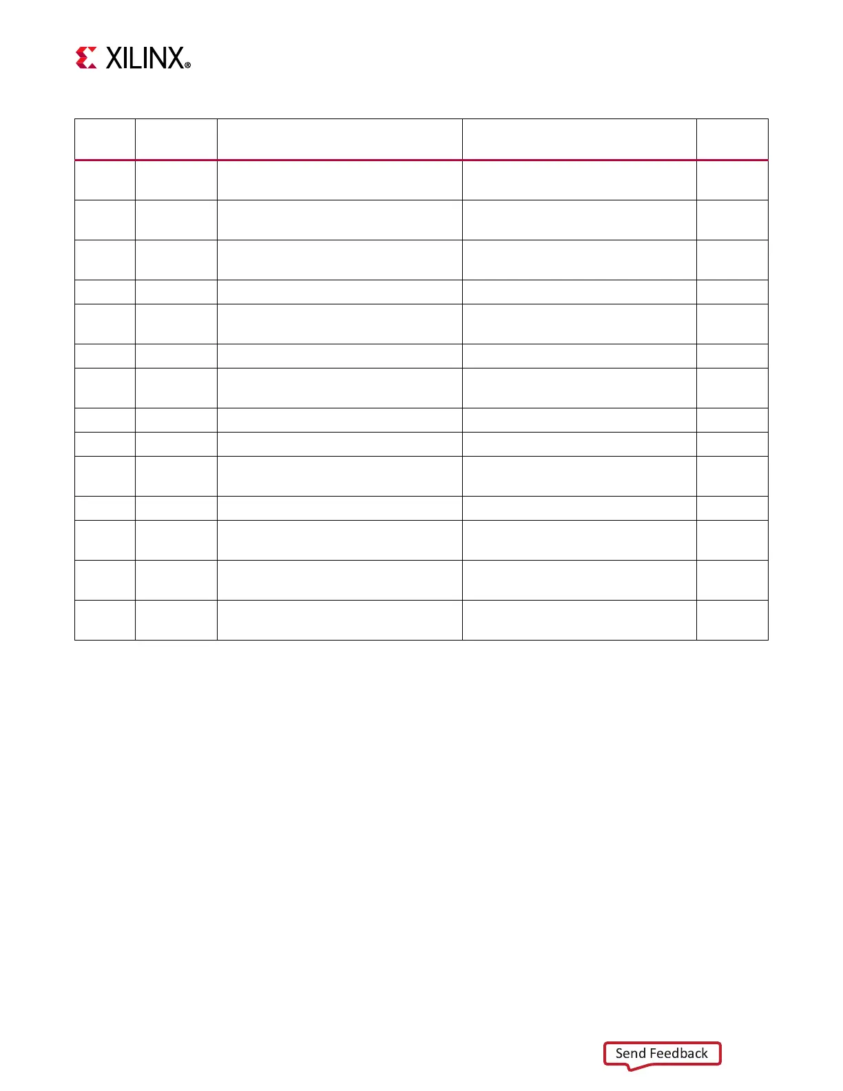
22 SW1
Switches
Power on/off slide switch)
C&K 1201M2S3AQE2 46
23 J52
Switches
(2 x 3 mini-fit receptacle)
MOLEX 39-30-1060 46
24 SW5
Switches
(PROG_B SPST pushbutton)
E-switch TL3301EP100QG 12
25 J5 FMC LPC Connector J5 Samtec ASP_134603_01 28
26 –
Board Power System (top and bottom
of board)
Maxim Regulators 47–60
27 P11 DPAUX (MIO 27-30) MOLEX 0472720001 34
28 J175 Monitoring Voltage and Current
Sullins PBC36SAAN
(1x3 0.1 male pin header)
44
29 U181 HDMI Clock Recovery [B] IDT8T49N241-994NLGI 31
30 SW6 Switches (MODE 4-pole DIP) 4-pole C&K SDA04H1SBD 12
31 U23
I2C1 (MIO 16-17) [B]
(8 Kb EEPROM)
ST MICRO M24C08-WDW6TP 33
32 U170 PS M.2 SATA Connector Amphenol MDT420M02001 38
33 J85 Jumpers (POR Override Sel)
Sullins PBC36SAAN
(1x3 0.1 male pin header
3
34 J12, J13 Jumpers (SYSMON I2C ADDR)
Sullins PBC36SAAN
(1x3 0.1 male pin header
3
35
J20, J21,
J22
Jumpers (POR circuit)
Sullins PBC36SAAN
(1x3 0.1 male pin header
12
Table 2-1: ZCU104 Board Component Locations (Cont’d)
Callout
Number
Ref. Des. Feature ([B] = bottom of board) Notes
Schematic
Page

 Loading...


