ZCU104 Board User Guide 80
UG1267 (v1.1) October 9, 2018 www.xilinx.com
Chapter 3: Board Component Descriptions
Switches
[Figure 2-1, callouts 20, 22, 24, and 30]
The ZCU104 board includes power, program, configuration, and reset switches:
• SW1 power on/off slide switch (callout 22)
• SW5 (PS_PROG_B), active-Low pushbutton (callout 24)
• SW3 (SRST_B), active-Low pushbutton (callout 20)
• SW4 (POR_B), active-Low pushbutton (callout 20)
• SW6 U1 MPSoC PS bank 503 4-pole mode DIP switch (callout 30)
Power On/Off Slide Switch
[Figure 2-1, callout 22]
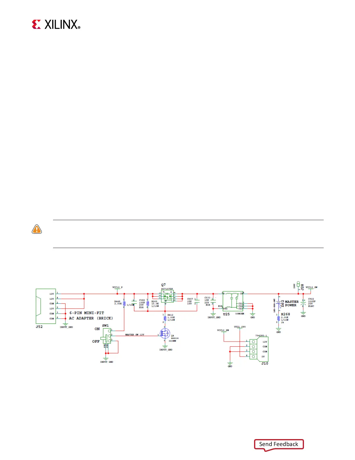
The ZCU104 board power switch is SW1. Sliding the switch actuator from the off to the on
position applies 12V power from J52, a 6-pin mini-fit connector. Green LED DS2 illuminates
when the ZCU104 board power is on. See Board Power System, page 83 for details on the
on-board power system.
CAUTION! Do NOT plug a PC ATX power supply 6-pin connector into the ZCU104 board power
connector J52. The ATX 6-pin connector has a different pin-out than J52. Connecting an ATX 6-pin
connector into J52 damages the ZCU104 board and voids the board warranty.
Figure 3-29 shows the power connector J52, power switch SW1, and LED indicator DS2.
X-Ref Target - Figure 3-29
Figure 3-29: Power Input

 Loading...


