ZCU104 Board User Guide 16
UG1267 (v1.1) October 9, 2018 www.xilinx.com
Chapter 2: Board Setup and Configuration
Switches
MPSoC Device Configuration
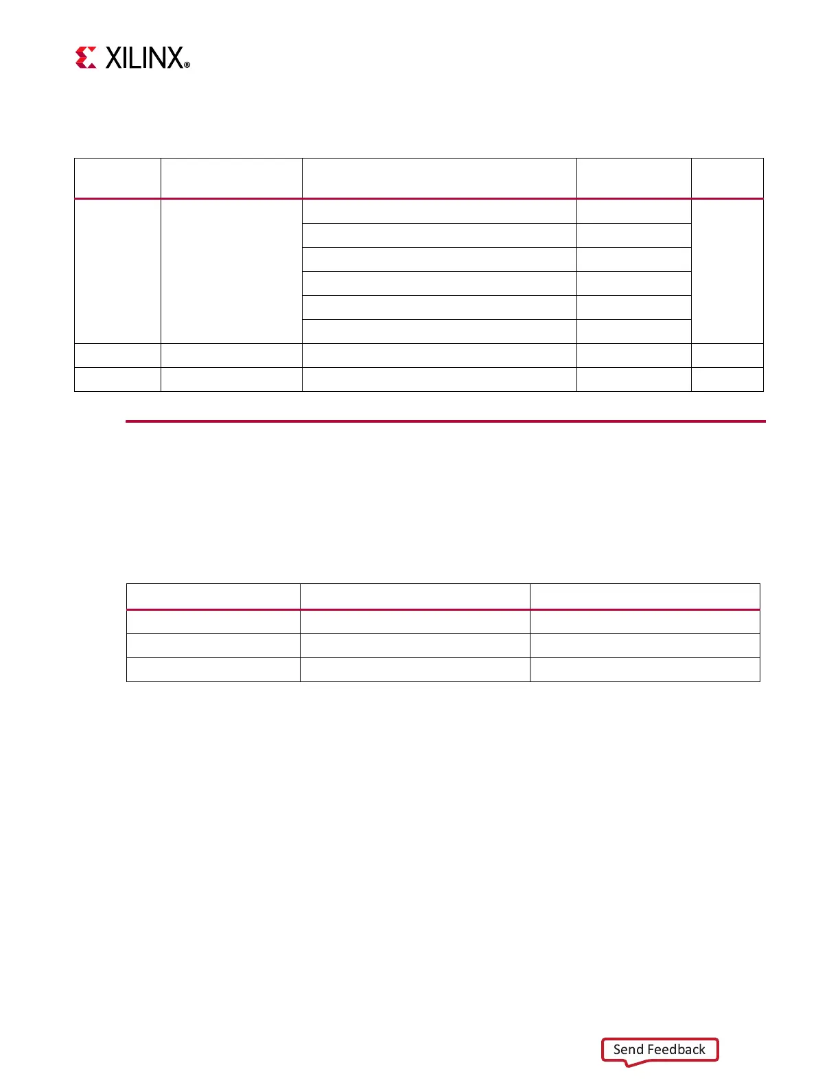
Zynq UltraScale+ XCZU7EV MPSoC devices use a multi-stage boot process as described in
the “Boot and Configuration” chapter of the Zynq UltraScale+ MPSoC Technical Reference
Manual (UG1085) [Ref 2]. Switch SW6 configuration option settings are listed in Table 2-4.
JTAG
Vivado®, SDK, or third-party tools can establish a JTAG connection to the Zynq UltraScale+
MPSoC device through the FT4232 Quad USB to multipurpose UART (U151) with micro-USB
connector (J164).
Table 2-3: Default Switch Settings
Number Ref. Des. Function Default
Schematic
Page
30 SW6
4-pole DIP switch PS_MODE select = [0010]
12
(ON = pull down, OFF = pull up = 1)
4: PS_MODE3 PS_MODE[3:0] = 0010 On
3: PS_MODE2 = QSPI32 boot default On
2: PS_MODE1 Off
1: PS_MODE0 On
17 SW13 4-pole DIP switch GPIO All Off 42
22 SW1 Main power slide switch Off 46
Table 2-4: Switch SW6 Configuration Option Settings
Boot Mode Mode Pins [3:0] Mode SW6 [4:1]
JTAG 0000/0x0 ON,ON,ON,ON
QSPI32 0010/0x2
(1)
ON,ON,OFF,ON
SD1 1110/0xE OFF,OFF,OFF,ON
Notes:
1. Default switch setting.

 Loading...


