ZCU104 Board User Guide 64
UG1267 (v1.1) October 9, 2018 www.xilinx.com
Chapter 3: Board Component Descriptions
User I2C1 Receptacle
[Figure 2-1, callout 21]
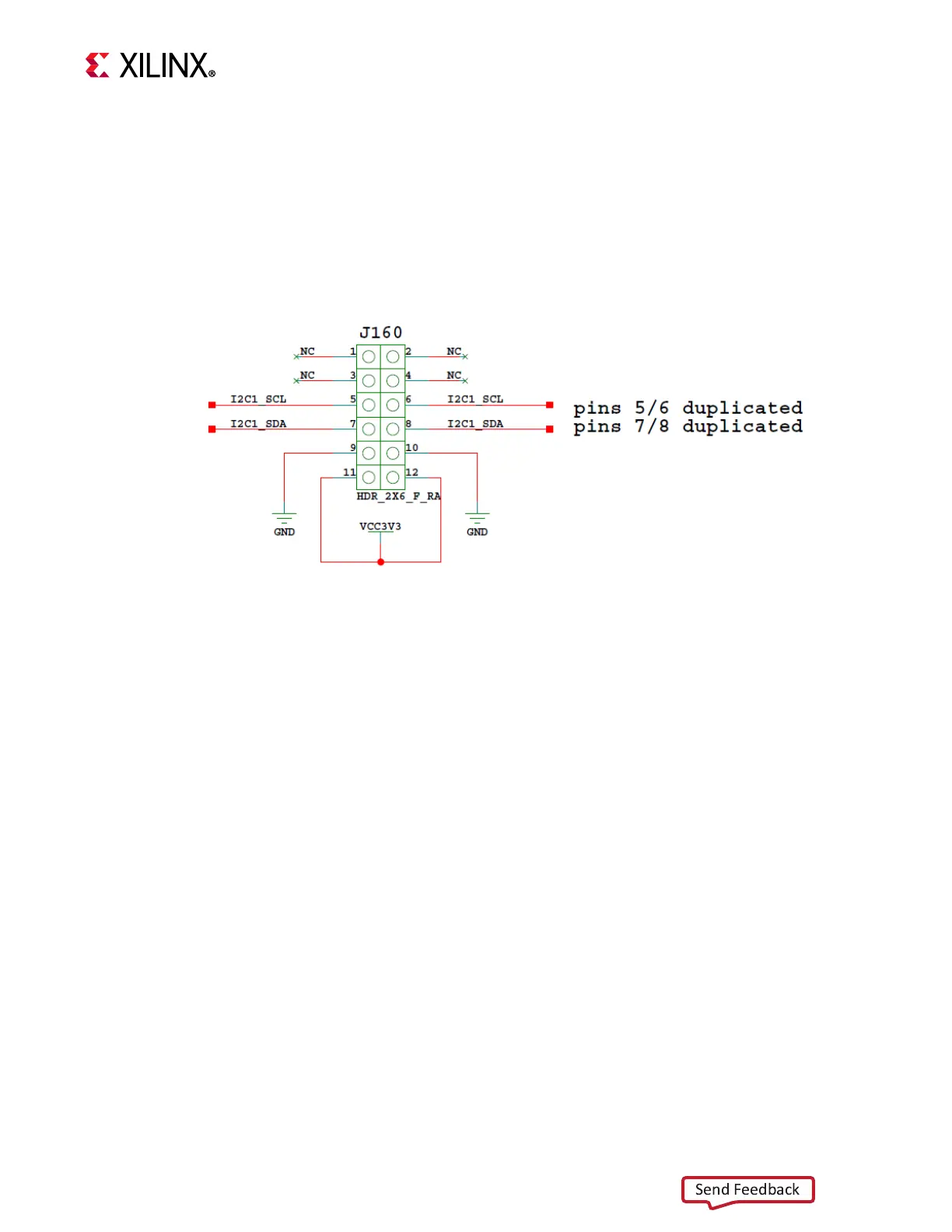
The ZCU104 evaluation board supports a PMOD 2X6 receptacle (right-angle female) J160.
Figure 3-21 shows the I2C1 PMOD receptacle J160. The I2C1 nets are a branch of the I2C1
main bus (see Figure 3-11, page 49). See the Digilent website [Ref 20] for more information
about the PMOD.
User I/O
[Figure 2-1, callouts 16-19]
The ZCU104 board provides these user and general purpose I/O capabilities:
• Four user LEDs (callout 16)
°
GPIO_LED[7-0]: DS38, DS37, DS39, DS40
• Four user pushbuttons and CPU reset switch (callouts 18 and 19)
°
GPIO_PB_SW[0:3]: SW18, SW17, SW16, SW14, SW15
°
CPU_RESET: SW20
• 4-position user DIP switch (callout 17)
°
GPIO_DIP_SW[7:0]: SW13
X-Ref Target - Figure 3-21
Figure 3-21: J160 PMOD I2C1 Right-Angle Receptacle

 Loading...


