EasyManuals Logo
Home>Xilinx>Motherboard>ZCU104

Xilinx ZCU104 User Manual

Xilinx ZCU104
92 pages
To Next Page IconTo Next Page
To Previous Page IconTo Previous Page
Page #62 background imageLoading...
Page #62 background image
ZCU104 Board User Guide 62
UG1267 (v1.1) October 9, 2018 www.xilinx.com
Chapter 3: Board Component Descriptions
User PMOD GPIO Connectors
[Figure 2-1, callout 14]
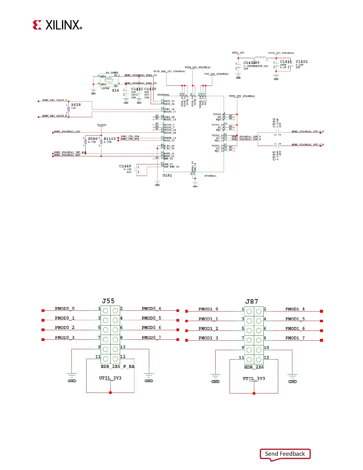
The ZCU104 evaluation board supports two PMOD GPIO headers J55 (right-angle female)
and J87 (vertical male). The 3.3V PMOD nets are wired to the XCZU7EV device U1 bank 87.
Figure 3-20 shows the GPIO PMOD headers J55 and J87. Table 3-23 lists the connections
between the XCZU7EV MPSoC and the PMOD connectors.
X-Ref Target - Figure 3-19
Figure 3-19: HDMI Interface Clock Recovery
X20259-020118
X-Ref Target - Figure 3-20
Figure 3-20: PMOD Connectors
X20260-020118
Send Feedback

Table of Contents

Other manuals for Xilinx ZCU104

Questions and Answers:

Question and Answer IconNeed help?

Do you have a question about the Xilinx ZCU104 and is the answer not in the manual?

Xilinx ZCU104 Specifications

General IconGeneral
BrandXilinx
ModelZCU104
CategoryMotherboard
LanguageEnglish

Related product manuals