VB5N series inverter
51
Range: P0.25~P0.07 basic running frequency
This group of parameters defines the flexible V/F setting modes of this inverter to satisfy the requirement of different loads.
Four fixed curves and one user-defined curve can be selected in P0.22.
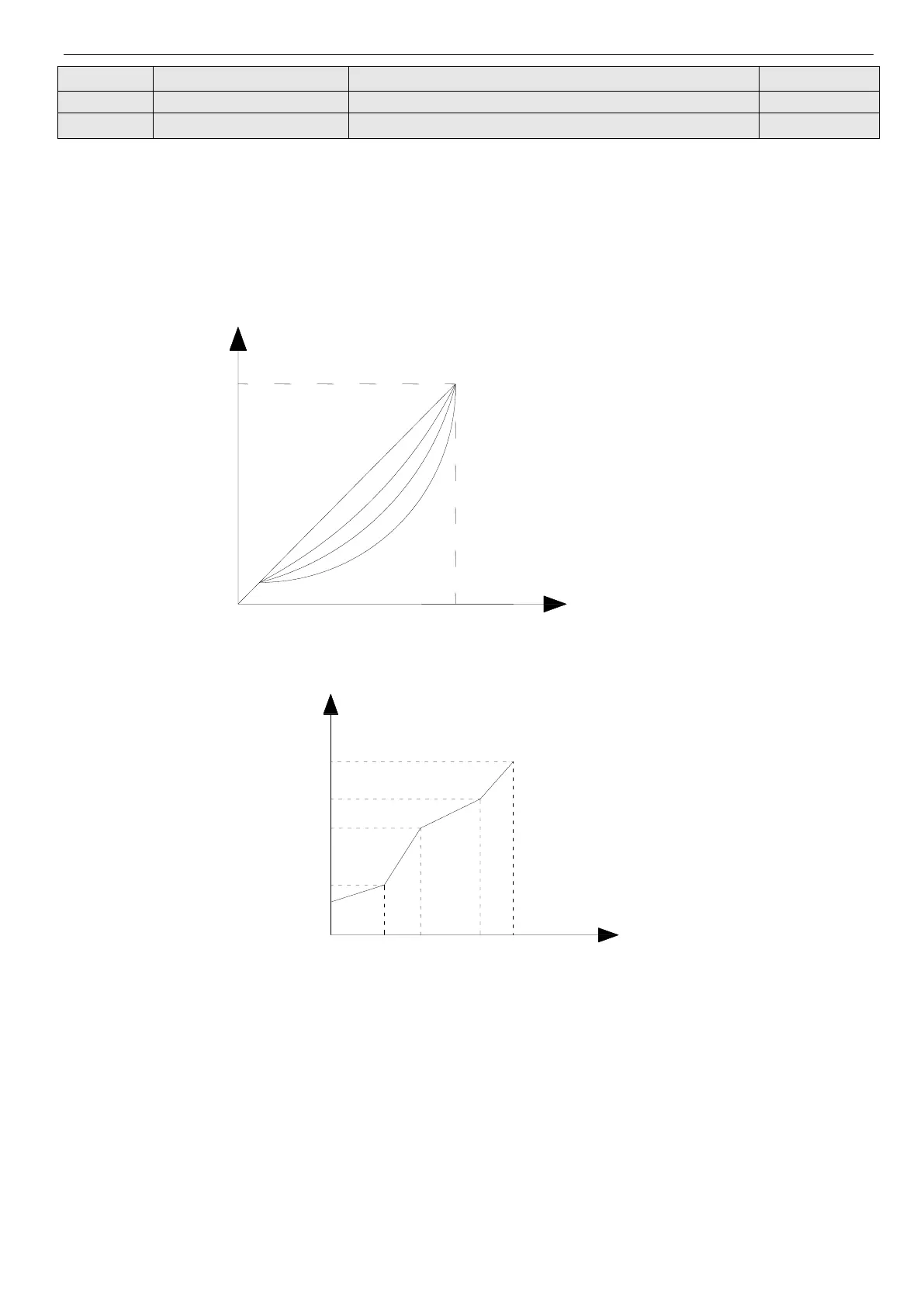
P0.22=0, V/F curve is constant torque curve, as shown in Fig.4-7 curve 0.
P0.22=1, V/F cuve is 1.2 powers torque-reducing curve, as shown in Fig. 4-7 curve 1.
P0.22=2, V/Fcuve is 1.7 powers torque-reducing curve, as shown in Fig.4-7 curve 2.
P0.22=3, V/Fcuve is 2.0 powers torque-reducing curve, as shown in Fig.4-7 curve 3.
To obtain the best energy-saving effect, user can select V/F curve 1, 2, 3 for fan, pump load.
Fig.4-7 V/F curve
Fig. 4-8 User-defined V/F curve
When P0.22 = 4, you can define V/F curve via modifying (V1, F1), (V2, F2), (V3, F3) to satisfy the special load require-
ment, as shown in Fig.4-8. Torque boost is suitable for user-defined V/F curve. In Fig. 4-8.
Vb =Torque boost(P0.09)× V1
V1-V3: multi-segment V/F curve
Segment 1-3 voltage percent
F1-F3: multi-segment V/F curve
Segment 1-3 frequency point
Vmax:max output voltage P0.08 Fb: basic running frequency P0.07
 Loading...