20 Troubleshooting
YASKAWA TOEPC7106171FD FP605 DRIVE INSTALLATION & PRIMARY OPERATION 115
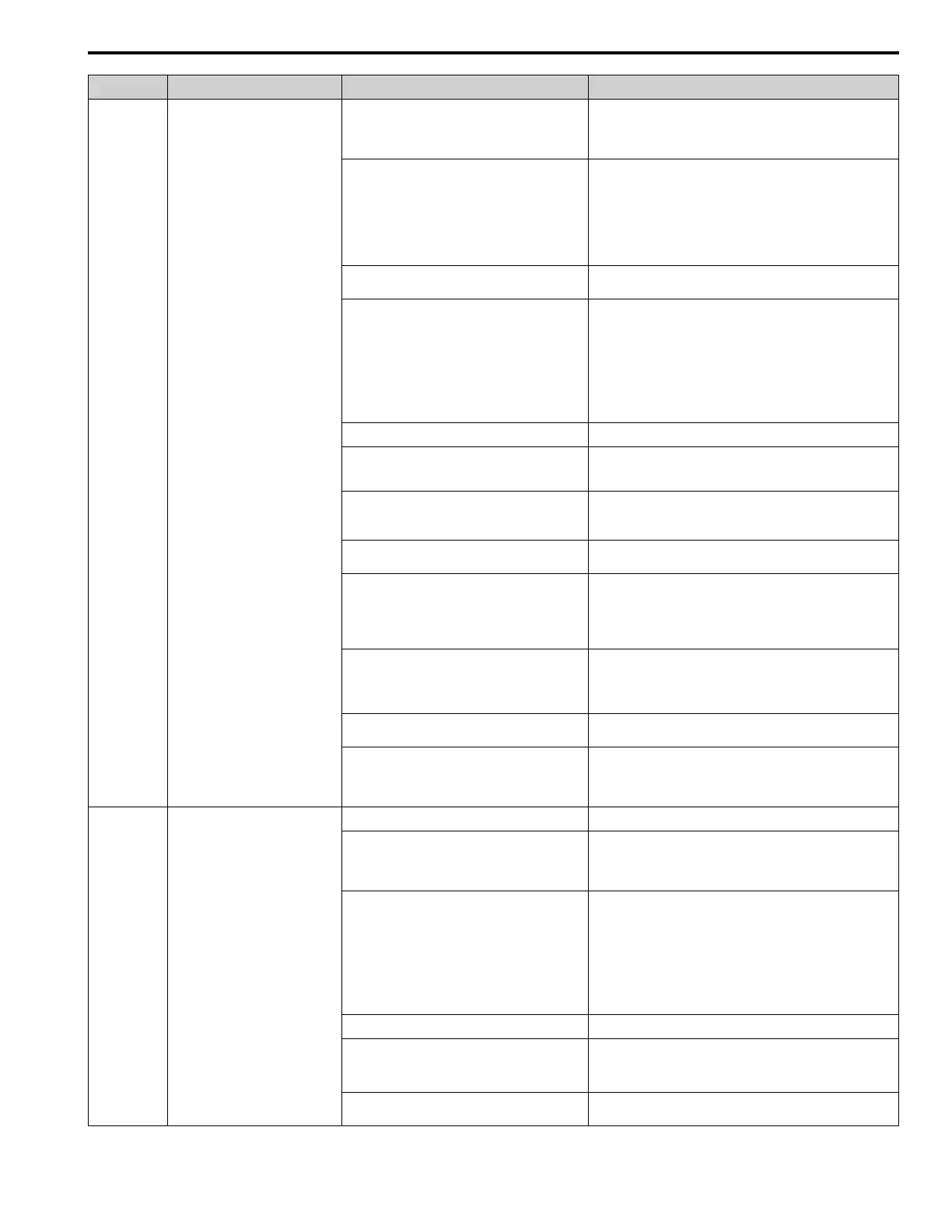
Code Name Causes Possible Solutions
The acceleration/deceleration times or cycle times are
too short.
• Examine the acceleration/deceleration times and the motor start/
stop frequencies (cycle times).
• Increase the values set in C1-01 to C1-04 [Acceleration/
Deceleration Times].
Overload occurred while running at low speed. • Decrease the load when running at low speed.
• Increase the motor speed.
• If the motor is run frequently at low speeds, replace the motor
with a larger motor or use a drive-dedicated motor.
Note:
For general-purpose motors, overload can occur while running
at low speed when operating at below the rated current.
L1-01 [Motor Overload (oL1) Protection] is set
incorrectly.
Set L1-01 in as specified by the motor qualities for a drive-dedicated
motor.
The V/f pattern does not fit the motor qualities. • Examine the ratios between the V/f pattern frequency and
voltage. Decrease the voltage if it is too high compared to the
frequency.
• Adjust E1-04 to E1-10 [V/f Pattern Parameters]. For motor 2,
adjust E3-04 to E3-10. Decrease the values set in E1-08 [Mid
Point A Voltage] and E1-10 [Minimum Output Voltage].
Note:
If the values set in E1-08 and E1-10 are too low, the overload
tolerance will decrease at low speeds.
E1-06 [Base Frequency] is set incorrectly. Set E1-06 to the rated frequency shown on the motor nameplate.
One drive is operating more than one motor. Set L1-01 = 0 [Motor Overload (oL1) Protection = Disabled],
connect thermal overload relay to each motor to prevent damage to
the motor.
The electronic thermal protector qualities and the
motor overload properties do not align.
• Examine the motor qualities and set L1-01 [Motor Overload
(oL1) Protection] correctly.
• Connect a thermal overload relay to the motor.
The electronic thermal protector is operating at an
incorrect level.
Set E2-01 [Motor Rated Current (FLA)] correctly to the value
specified by the motor nameplate.
There is increased motor loss from overexcitation
operation.
• Lower the value set in n3-13 [OverexcitationBraking (OEB)
Gain].
• Set L3-04 ≠ 4 [Stall Prevention during Decel ≠ Overexcitation/
High Flux].
• Set n3-23 = 0 [Overexcitation Braking Operation = Disabled].
The speed search-related parameters are set
incorrectly.
• Examine the settings for all speed search related parameters.
• Adjust b3-03 [Speed Search Deceleration Time].
• Set b3-24 = 1 [Speed Search Method Selection = Speed
Estimation] after Auto-Tuning.
Phase loss in the input power supply is causing the
output current to change.
Make sure that there is no phase loss, and repair problems.
Overload occurred during overexcitation deceleration. • Decrease the value set in n3-13 [OverexcitationBraking (OEB)
Gain].
• Decrease the value set in n3-21 [HSB Current Suppression
Level].
oL2 Drive Overload
The load is too large. Decrease the load.
The acceleration/deceleration times or cycle times are
too short.
• Examine the acceleration/deceleration times and the motor start/
stop frequencies (cycle times).
• Increase the values set in C1-01 to C1-04 [Acceleration/
Deceleration Times].
The V/f pattern does not fit the motor qualities. • Examine the ratios between the V/f pattern frequency and
voltage. Decrease the voltage if it is too high compared to the
frequency.
• Adjust E1-04 to E1-10 [V/f Pattern Parameters]. Decrease the
values set in E1-08 [Mid Point A Voltage] and E1-10 [Minimum
Output Voltage]. For motor 2, adjust E3-04 to E3-10.
Note:
If the values set in E1-08 and E1-10 are too low, the overload
tolerance will decrease at low speeds.
The drive capacity is too small. Replace the drive with a larger capacity model.
Overload occurred while running at low speed. • Decrease the load when running at low speed.
• Replace the drive with a larger capacity model.
• Decrease the value set in C6-02 [Carrier Frequency Selection].
The torque compensation gain is too large. Decrease the value set in C4-01 [Torque Compensation Gain] to
make sure that the motor does not stall.
 Loading...